I started off my day thinking I'd take my ESP32 for a JTAG test drive. Searching for pinouts I quickly realized there are known bad pinouts floating around. This was quite a surprise as the ESP32 has been out for well over a year. I wasted a ton of time on that. I'm posting my findings here.
As one might expect - the Adafruit pinout appears to be the most accurate one:
 |
| WROOM-32 ESP32 Pinout |
(many thanks to the folks at @esp32net for responding to my tweet and helping to identify correct pinout).
So if you happen to see the pinout on the sparkfun site, the information is WRONG (hopefully they will correct it soon):
https://www.sparkfun.com/news/2017 (bad pinout here!)
I modified a known-good pinout image to create this little reference to easily identity a bad ESP32 pinout. Hint: look for the locations of the GND pins.
 |
| Not all online pinouts are accurate. Here's where to find proper GND on ESP32 |
Really, the ultimate authority is of course the Espressif data sheet:
The PDF has this pinout overview, with the functions listed in a table on the following pages of the PDF:

See also the Espressif ESP-IDF docs on GitHub:
Ok, so once the correct pinout is found - there was a moment of "oh no, all the JTAG pins are not available on my CoreBoard V2 breakout (grumble, grumble I don't want to solder them on)". But no... all good. Who would think that SD2 = TCK?
I should mention that "ESP32_Core_Board_V2" is the same as "ESP32-DevKitC"
Resources available here:
In particular the PDF of schematic found in "ESP32 Development Board Reference Design":
found in the zip buried in this directory:
ESP32_Development_Board_Reference_Design\ESP32-DevKitC(ESP32_Core_Board_V2)\01_Schematic

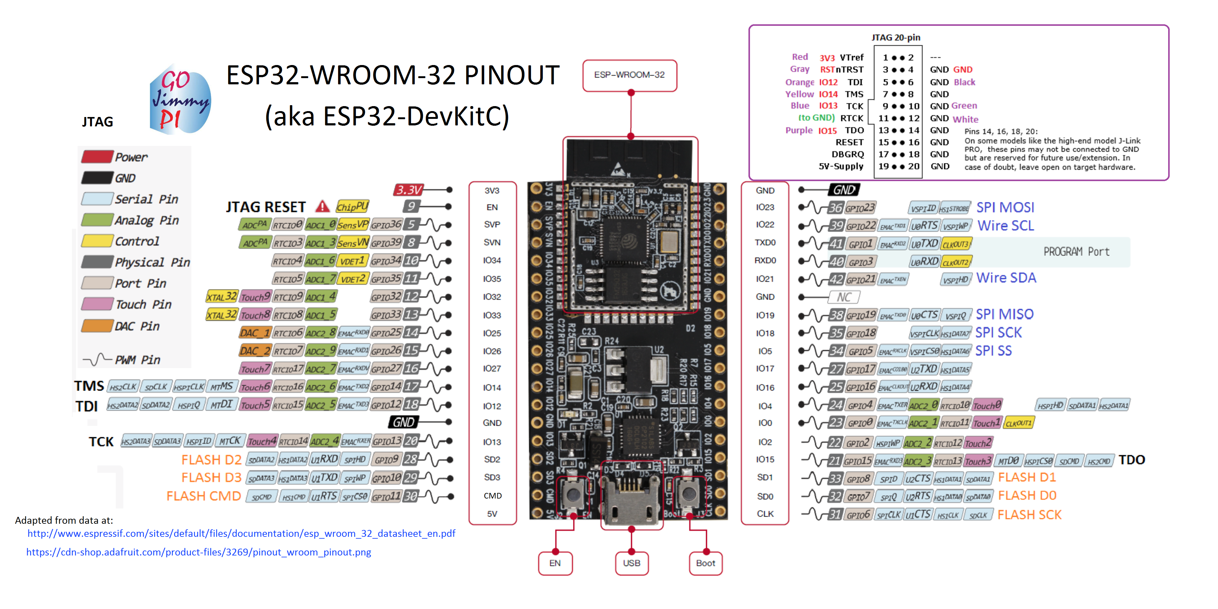
I took a variety of sources and copy/pasted into a new pinout diagram for myself:

This one is the whole dev board and includes the 20 pin JTAG header, and my (arbitrary) color code:
 |
| ESP32-WROOM32 Pinout for ESP32 DevKitC / ESP32_Core_Board_V2 |
So these days, I've been really enjoying the JTAG capabilities of the Sysprogs VisualGDB:
They have a tutorial for ESP32 JTAG here:
Online tutorials are really awesome. I wonder how long it would have taken me to figure out Step 7 on my own! ha! (issue with Visual Studio/ESP-IDF framework and optimization default problem: who would have guessed?)
But that tutorial is using the Sparkfun ESP32 Thing, and mine is the Adafruit ESP32 Core Board V2, mentioned above.
Note: Although the Sparkfun apparently has an LED on GPIO5 - according to the schematics, the only LED on this board is the power LED - so don't expect it to blink - unless you are having really serious power problems! ;) But the sample code does indeed control GPIO5.
There's a recommended max of 6mA per pin on ESP32, with and absolute max of 12mA (read: you could still damage or shorten life). Many LED's run at 20mA and drop 1.8V. At (3.3V - 1.8) = 1.5; this means you should be using at least a (1.5/0.006) = 250 or 270 ohm resister for only 6mA. This may not result in a very brightly illuminated LED.
Here are a couple of hookup pics:
 |
| JTAG connections for ESP32 |
 |
| JTAG connections to Segger J-Link for ESP32 |
For information on VSCode debugging of ESP32, see this post.
My success tweet: https://twitter.com/gojimmypi/status/842861378801086464
Visual Studio 2017 source code for ESP32 JTAG Tutorial:
As a bonus, the tutorial is based on freeRTOS (I think all of the ESP32 code is using that). There's a pretty good UDemy FreeRTOS class that I'm taking:
Where to buy:
See also: http://esp32.net/ (this site is so comprehensive, I should say "start here first!")


Hi, I am trying your setup for debugging an ESP32 with a Segger J-link, however it fails to flash the ESP32 with a Not Responding error. The test settings button does indicate all is correct.
ReplyDeleteIn your picture of the J-Link connection, you have a brown wire to the ESP32 ground, but on the J-Link connector it looks like it is hooked to pin-2 which is NC.
Do you have any thoughts?
That's an astute observation! I agree that the pin in the Segger is NC, and is likely a leftover during my trial-and-error phase - as when googling "segger j-link pinout" oddly some of the pics will show Pin 2 as TRST.
ReplyDeletehttps://www.segger.com/interface-description.html
I will recheck my wiring soon and confirm - but in the meantime, I suggest you check out VSCode (no, seriously!). It has amazing debug capabilities - although I did need to run OpenOCD server on an Ubuntu VM. I have another blog that talks about that just this month (May 2017)
hmm.. other ideas: I assume you've also tried the usual power cycle of Segger? You are powering the ESP32 separately, too - right - with a known good cable (try a different one)? Be careful of ground loops.
It keeps telling me some GDB command fails to complete when attempting to flash the ESP32. It tries 3 times then gives up. I am powering the ESP32 from the USB cable with a tested cable.
ReplyDeleteDid you make any other setting changes in VisualGDB to get this working? Here is a reply to my question from Sysprogs:
ReplyDeleteGenerally, ESP8266 and ESP32 are much less reliable than ARM-based models and often require experimenting with various options in order to get everything working. If you are looking for a solution that works out-of-the-box, we would recommend CC3200, otherwise feel free to post details on the FLASH programming errors you get and we will try to suggest a solution if this is something known.
Hi Tom - Yes, I had similar comments from the sysprogs team regarding JTAG debugging of the ESP devices. I don't recall if I made any other VS settings, but you can see my source files here:
ReplyDeletehttps://github.com/gojimmypi/ESP32/tree/master/ESP32-JTAG-VisualGDB
It has been a couple of months, and I don't recall if needed for JTAG as well as USB programming... but are you holding down the flash button while powering up the ESP32?
I had a lot of problems using an FT cable as well. In the end what helped get things moving was to change the alg_timeout to 10 seconds in the debug-vgbsetting file, which is part of the project. It defaults to 5 seconds which is not long enough for the flash to erase.
ReplyDeletecom.sysprogs.esp32.openocd.alg_timeout
10000
Today I reconnected the J-Link and it was working.
Did you change this in your setup?
Hi !
ReplyDeleteVery interesting article. Can you tell we where you found the ribbon cable with separated pins you use on your JLINK ?
Thank you. :) They are called "Dupont Wire Jumpers" - I got mine from one of my favorite sellers on ebay: http://stores.ebay.com/TxHang-Electronic/_i.html?_nkw=wire+jumper&submit=Search - handy to have M-M, F-M and F-F
DeleteThanks for the article and pics. I got GDB working with ESP32 devkit C and J-Link EDU. I am unable to get System View trace working. Not sure if it's a license thing on the J-Link or if I'm doing something wrong. I ordered a FT2232H board to see if that makes a difference.
ReplyDelete