Tuesday, October 24, 2017

ATECC508A Embedded Crypto - AWS costs

TL;DR;  Dont leave aws_interact_gui.py running!

In my previous post, I wrote about my first impressions setting up AWS.

This is just a quick blog post to show my crazy AWS charges after just a few days. Actually, not so much the cost, but the number of messages:


Note that my AWS IoT monitor has recorded less than 20 connections.


Also on that page, just a bit further down - shows I've only published a few hundred messages:

And only 2 rules executed:


Yet somehow, I've been charged for hundreds of thousands of "messages". The curious thing, is they are listed under the "Shadow Message".

So ok - 2 bucks is not a big deal... but scale that for more devices and more than a few days - and the costs get out of hand really rather quickly.

I've posted a message on the AWS forum requesting help in understanding these charges. I'm wondering if simply launching the shadow monitoring page... if there's perhaps there are repeated messages from the browser to my device such as this shadow monitor:
I've contacted AWS billing, but they have "limited access" to give me any more details as to exactly how those hundreds of thousands of messages occurred.

Fortunately, the folks at Microchip are super responsive. I had an answer within hours! (Thanks, Ben!) The forum answer copied here:

The demo GUI (aws_interact_gui.py), polls the GetThingShadow (http://docs.aws.amazon.com/iot/latest/developerguide/API_GetThingShadow.html) API function to show the current shadow state. However, if left running, its polling period of 500ms could incur a lot of messages.

This polling method was not intended to be an example of how an IoT system would interact with the devices, but just a quick and easy way to display the state. Typically, one would use the IoT rules engine to trigger other actions within AWS:http://docs.aws.amazon.com/iot/latest/developerguide/iot-rules.html
We're looking into changing how this script works so leaving it running doesn't create so many messages.

So the super important take-away here is to NOT leave the aws_interact_gui.py running (at least not until updated)! At 500ms intervals (2 per second), that would be 31*24*60*60*2 = 5,356,800 messages per month! Even at $5 per million messages, that's $30 a month just to leave the diagnostic app running.

Stay tuned... I'm now digging into the RTOS code which is really quite interesting :)


Saturday, October 14, 2017

ATECC508A Embedded Crypto - Next Impressions setting up AWS

The state of Internet of Things (IoT) Security is a disaster. Hardly a day goes by without news that some new product is discovered to also have some ridiculously glaring security problem. There's a potential solution: a "security in a chip" device for less that a buck, that could seriously change the landscape of IoT security.

In my previous post, I took the MicroChip AT88CK590 for a brief initial test drive. Although cool in concept, I was initially frustrated and underwhelmed. I didn't even get around to posting my experience for a couple of months. (in part, as I never actually got it doing what I wanted) Note that was with completely different eval hardware.

This time around I am looking at the much more elaborate Zero Touch Secure Provisioning Kit for AWS IoT. Be sure to pay attention to the "-B" suffix. A similar part number at mouser is marked as "End of Life: Scheduled for obsolescence and will be discontinued by the manufacturer." You can try this link to see if they eventually carry the update.

 AT88CKECC-AWS-XSTK-B, image from MicroChip


However, when I did finally post that blog page and tweeted it - I got the attention of the folks at MicroChip. In particular their response regarding the a new and interesting crypto chip AWS walk-through that I had not seen:

http://microchipdeveloper.com/iot:ztpk

I starts out really quite interesting! The steps are very clearly documented regarding all the (less-than-intuitive) AWS setup details. At the end of the story though, right before the culmination of anticipated technical details, it abruptly ends. I was really hoping for a code walk-through as well. Alas there was just a single "Explore" bullet item:
  • "Firmware that comes in the ZIP to see how the ARM SAM G55 communicates with the secure element (ATECC508A) and the Wi-Fi module WINC1500"
So, ok. I'm good with doing my own code analysis. Sometimes the comments are better than an external document walk-through anyhow.

There are a ton of links throughout the rather long instruction set. By the time you get to the end when reading, perhaps the Zero Touch Secure Provisioning Kit Software Files was missed way up at step 2. I had see that, even clicked on it. But it initially looks like an ad, complete with the "Buy It Now" button in the upper right corner. But the software is there! Scroll to the bottom and click the "Getting Started" tab:


Then click on the "Get the necessary code HERE" link:


I would have included the link, but it goes to a wonky "Software Copyright" page where you need to provide a name, email, company info. You can however, then immediately download the software. (unlike some sites where you need to wait for confirmation email, bla, bla).

I had a very difficult time with this: several times when I downloaded the file, it was less than 50KB and windows reported that it was correupt when trying to open it. Fortunately my twitter thread ended up with an offer to talk with someone at MicroChip! Later that day I had a great phone conversation with a rep from MicroChip that completely re-invigorated my interest in their crypto chip! He also helped with the download. What worked for me is copying the (apparently time-sensitive) link to clipboard... closing google chrome... and then pasting into a new chrome instance. I think there may have simply been a problem with the timing/loading of the javascript for the page. In any case the file starts downloading immediately. It is about 13MB in size.

The two main components of the zip are the (1) python scripts for setting up AWS and (2) a SAMG55 Atmel Studio Project called AWS_IoT_Zero_Touch_SAMG55.atsln

It is unfortunate that the code is "protected" behind a copyright notice. It really belongs as open source on github. Hopefully MicroChip will change that soon.

I suspect the folks at AWS are really quite happy to see they are the only IoT service listed! lol


The microchipdeveloper site is of course still a work in progress. I hope to see a lot more providers in the future. I've always been wanting to use AWS for my MQTT data anyhow: In part, well, it is MY data. I had tried the very easy to use Adafruit.io - but some time back it was offline for a long stretch. (granted it was still beta) But also - it has limitations on number of devices (5) or pay $120/year for up to 60 devices (not yet available), and show stopper: the data was out of my control. The cool thing about adafruit.io was that I could use insecure MQTT of plain HTTP with my ESP8266 (well, duh, back to the proliferation of insecure IoT, eh?) AWS is definitely more challenging in not even allowing anything but a secure connection.

One thing to point out about installing AWS CLI for Windows is that at the end of install, nothing happens. No new icons, no message of completion. Nothing. For me, the "AWS Tools for Windows" listed under Amazon Web Services in Windows 10 start menu - was something I installed last year.

To confirm AWS CLI installed correctly, simply pop into a DOS window and type "AWS":


Microsoft Windows [Version 10.0.15063]
(c) 2017 Microsoft Corporation. All rights reserved.

C:\Users\gojimmypi>aws
usage: aws [options] <command> <subcommand> [<subcommand> ...] [parameters]
To see help text, you can run:

  aws help
  aws <command></command> help
  aws <command></command> <subcommand> help
aws: error: too few arguments

C:\Users\gojimmypi>


The Python install is a little tricky for me. I already had V2.7 installed (for something that explicitly wanted that version)... and to add V3.6.3 to my path... well, I'm sure I'll bump into that at some unexpected point in the future. This is a good reason to perhaps have a VM for each development environment.

The comment "May take a while to install." should not be underestimated for the pip install step! They should change the text to: "Takes a ridiculously long time, and may seem to stop at times!" lol!

Another place to note a possible problem is on creating roles in Section III. I think the AWS console changed a little since the MicroChip instructions were created. Here's my AWS Console:


Note the "AWS Service" is selected (no radio button) and the service is called simply "Lambda" (not AWS Lambda). Next Step is actually labeled "Next: Permissions"

The final resultant JITR policy also looks a bit different from the walk-through.


My function "Author from Scratch" was also a bit different than instructions:

Instructions:


What I saw:


And here's what my actual code looks like in the function:


The instructions refer to "Rules"... it is now called "Act". Note there's an identical icon, just a different name (instructions on left; my AWS console on right):


The instructions also show running a python script as easily as if it were a batch file. I needed to use the word "python" before the script name:


I received an annoying error:


I wasted a ton of time before I realized somehow Windows 10 "set time automatically" was turned off! Argh! So a click of an option setting and VOILA! Success.

<happy dance>!!</happy dance>

Next, I will finally take a look at the code!

Check out my next post on my first bizarre AWS costs.


Tuesday, October 10, 2017

ATECC508A Embedded Crypto - First Impressions

Having an embedded crypto chip to offload SSL processing for say, an ESP8266 sounds really quite interesting - particularly a solution that could be housed in a package as small as a tiny 3-Lead SOT-3 package! Wow, how cool would that be to help solve the problem of plain text IoT devices on devices with limited processing power and memory?

First, I'd like to thank @MartyMacGyver for his time and assistance in helping me to better understand the Atmel crypto chips and related development boards. Be sure to see see his CryptoAuth-explorations. As with his information, this project is neither affiliated with nor sponsored by Microchip / Atmel.

My AT88CK590 from Mouser Electronics arrived last week! (erm, by the time I published this, actually a couple of months ago). Atmel has apparently not heard of "Frustration Free Packaging". Petty cardboard complaint aside, even the cheap plastic USB cap was very difficult to remove. Alas only twenty bucks, but you'd think that they'd want to make a better first impression with a developer kit, eh? Besides, you'll probably want to pry it open anyhow. I took a soldering iron to mine and flattened the bumps that hold the USB cover in place to make it easier to remove.

I first upgraded Atmel Studio (Help - Check for Updates). That took quite some time. Next I installed the ACES 5.0.0 Setup from the ATT88CK50 page. You must have a device to use the software. Otherwise nothing but the "No devices" dialog box:


Once you plug in the device, the dialog box will change:


Note that the AT88CK590 USB dongle has 3 different security chips on it, each with 3 different I2C addresses. These three chips are controlled by the onboard ATmega 8-bit Atmel AVR® AT90USB1287 microcontroller. The complete AT90USB1287 datasheet is a whopping 456 pages long, There's also a summary datasheet that's only 39 pages. The schematic diagram is likely useful for review.

The important thing here: when test driving the crypto-chips directly on the USB dongle, code will target the ATUSB1287. Code will also need to be portable to your target MCU,

While reviewing the schematic, you'll see that the USB port talks *only* to the MCU, Only the MCU talks on the I2C bus to the security devices. Thus if you put different firmware on it, you could well find yourself no longer able to use the ACES software to talk to the security chips. Program with caution!

As a side note, when using Atmel Studio, here's a list of the supported programming tools for the ATUSB1287. Probably the most important one is that last DFU item.


The so-called "walk-through"s in the AECS Config help were less than impressive. I swear the help looked the same as those found in Windows 3.1 - and worse: the contents also did not fully match my app. For example: there was no green indicator for system status:


Next, there was no mention of the most important point - that the Key ID number for step 2 needs to match Key ID in step #3.  Obvious of course once you know this - but for first time users following a Walk-Through... hmm.


So anyhow, type a challenge phrase, press the [Execute Nonce] button, then [Execute Mac] then [Execute CheckMac]. If successful there should be a Matched status.

The ATAES132 walk-though is even less complete & less helpful.


There's only online help for 2 of the 3 chips: the ATSHA204 and and ATAES132. Of course my ATECC508A is not listed. :|  The only reason I ordered this evaluation kit was to take that chip for a test drive. After a bit of digging, I eventually discovered "The ATECC108A and ATECC508A are supersets of the ATSHA204A and thus upward compatible". I was unable to find a full datasheet for the 508 - however once knowing that it is a superset of the ATSHA204A, one makes the assumption that the datasheet is (hopefully) "similar enough" to the 508.

An important piece of information in the ATSHA204A datasheet (page 14, Section 2.1.3):
"The OTP zone of 64 bytes (512 bits) is part of the EEPROM array, and can be used for read-only storage. 
Prior to locking the configuration section (using lockConfig), the OTP zone is inaccessible and can be neither read nor written. After configuration locking, but prior to locking of the OTP zone (using lockData), the entire OTP zone can be written using the Write command. If desired, the data to be written can be encrypted. When unlocked the OTP zone cannot be read."

Once you start the AECS Config tool, it appears there is no way to select a different chip to test drive. So exit and restart the app to choose a different one.

Upon restarting and selecting the 508, I was not able to get the Verify Mac to work. It appears that although the other two chips are pre-configured, this one is not. That may be expected in the stand-alone chips. I had asked mouser if I could buy individual quantities of the ATTEC508A-SSHAW (the ones pre-configured for AWS) - but unfortunately they responded indicating that they could not break the 4000-piece reels. Still I would have expected the  ATT88CK50 to arrive pre-configured with something even if the individual 508's that I also bought were blank.


So also take note of the downloads on the Atmel site. The first two code samples after the ACES software are for the ATSHA204 chip, not the ATECC508A.

The last download, the Atmel-CryptoAuth-AT88CK590_Project-C-code.zip has over 3000 files. Alas that too, seems to be limited to the SHA204 and AES132 libraries. Cool if that's what you are looking for, but I was hoping to dig into the new '508s (the third and most interesting of the chips!)

So back to the Atmel/Microchip web site... <sigh> and I came across this page on ECC-based Crypto Elements. Clicking on "start now" takes you to yet another crypto page. Chasing the links and you'll find the AT88CK101 Development Kit. Finally on THAT page, there's a link to the CryptoAuthentication ATECC108A/508A Development Library 1.2.1 download. This is the eccX08_library-150525 with a brief README and some C header and source files; not much of a walk-though here, but code is interesting.

As for the AT88CK101 - well Mouser has 6 similar but different products listed, Each are about $90 but none of which list the ATECC508A. So I'm not sure if it would be useful or not with the '508.

Continuing to chase the links, you'll see further down on the Start Now page, that there's a link to CryptoAuthLib.  And on THAT page, there's a link to the CryptoAuthLib Firmware Library 20160108. This is a 12MB compressed zip with many more interesting files. I'd start with the .\cryptoauthlib\docs\README.pdf then move on to .\cryptoauthlib\docs\html\index.html where there's finally some good docs! Also see there's a doc tab, with even more downloads.

I was not able to find this code in the Atmel github repository, nor the MicroChip github respository. However, MicroChip does have this github cryptoauth-openssl-engine repository that is definitely worth a look. The README there starts out with: "This is an OpenSSL Engine implementation using ATECC508A for ECC key storage, ECDSA sign/verify, ECDH, and FIPS Random Number Generator" and there's a cool wiki as well.

After finding the MicroChip github, I realized that there's an entirely different subset of documentation and downloads for the ATECC508A available, separate and different from Atmel. Apparently a cohesive and consistent web site has not been a priority after the acquisition.

I really prefer that code be available on github, rather than zip downloads. So I copied what I believe are the most relevant source files to my own atmel-code repository. My github clones are stored in \workspace\ directory, so be sure to start with:

\workspace\atmel-code\cryptoauthlib\docs\html\index.html

After getting all this installed, I just happened to be lucky enough to be on the github notification email alert for issue #1 and there.. a link in the MicroChip site to this updated CryptoAuthLib gem (updated  July 5, 2017). Note the CryptoAuthLib link above, specifically the  Atmel-CryptoAuthLib-Firmware_20160108.zip is noted on this new page as "Not recommended for New Designs" - note there's also no indication of this new firmware on the Atmel CryptoAuthLib page!

If you download that updated zip file - in the README.md there's a note to watch the CryptoAuthLib documents (on the Atmel site) for "new examples coming online". (as of the timw of my writing this, there's noting newer than January of 2016). I wonder why MicroChip would post new code on the Atmel site, referenced from a download from the MicroChip site?

Revisiting the mod topic, the Atmel Flip 3.4.7 as mentioned here does not seem to work on Windows 10. Both the "requires Java Runtime and "Jave Runtime Included" return an error message:

The newer (January 2017) flip program on the MicroChip site is actually an older version 2.4.6 from 2002 that only supports a limited number of chips such as the 89c51 series.

Fortunately I happened to already have a Windows 7 machine setup in a VMWare Workstation, Upon running the same setup there, I was able to get the Flip utility working. However not much more than that - as after selecting an MCU, I received this error complaining about a missing libusb0.dll


The issue here, is that apparently the Atmel drivers needs to be manually installed/updated. Once again, thanks @MartyMacGyver for the tips on replacing the AT90USB1287 drivers on Windows 7. Here, just go to Control Panel - Device Manager. Right-click on the Atmel Device and select "Update Driver Software...".


Then manually select the Atmel Flip directory:


(as usual, you may be prompted to reboot)

Curiously, not only do I have the Java Virtual Machine problem on Windows 10, but I also don't see the Atmel device listed anywhere in device manager. Windows 10 *does* see it, as I am able to go into VMWare workstation and connect the host device to the Windows 7 VM. Hmm.. I'm not sure I want to fire up a Windows 7 VM every time.

So at this point, I am really quite underwhelmed, unimpressed, and rather disappointed and frustrated. I am also however - rather relentless. A bit of googling and of course I immediately found others with the same problem on the avrfreaks site. Fortunately the AT90USB1287 is DFU Bootloader Capable, and my old friend avrdude is a DFU loader! There are a variety of avrdude tutorials out there, including this one from lady ada. If you have the Arduino library installed on Windows, you likely have avrdude installed here:   C:\Program Files (x86)\Arduino\hardware\tools\avr\bin (and it likely will not be in your path).

The first thing we'll want to do is read and save the firmware!


"C:\Program Files (x86)\Arduino\hardware\tools\avr\bin\avrdude.exe"
"C:\Download\Atmel\Atmel-CryptoAuth-AT88CK590_Project-C-code_1-0-5\DevelopmentKits\AT88CK590\CombinedLibraries\AtmelStudio6\CombinedLibraries\OutputConfigDefault\"

gives an error:


avrdude.exe: can't open config file "": Invalid argument
avrdude.exe: error reading system wide configuration file ""

so I tried on linux (Ubuntu)


avrdude -pusb1287 -cflip1 -Uflash:r:read-usb1287:a

different error:


avrdude: Error: No matching USB device found
avrdude: AVR device initialized and ready to accept instructions

Reading |                                                    | 0% 0.00savrdude: error reading signature data for part "AT90USB1287", rc=-1
avrdude: error reading signature data, rc=-1

avrdude done.  Thank you.

it appears that when plugged in, there are 2 new /dev/ items:

/dev/hidraw1
/dev/usb

I tried to change permissions, no luck there.


sudo chmod 777 /dev/usb
sudo chmod 777 /dev/hidraw1

Same avrdude error. A bit more googling and I found this note that you need to first boot the usb1287 into DFU mode. As yes, just as @MartyMacGyver described in his wiki on entering DFU mode. After chasing documentation and other software issues, I had almost forgotten about his great walk-through that includes valuable DFU info.

I simply want to have an embedded solution for SSL. They certainly don't make it easy. Just out of curiosity, I thought I'd poke around and see what sort of alternative solution might be available. One of the tools appears to be the AT88CK9000 Secure Personalization Kit. Alas, that too turned out to be a comedy of "not available":


I at least found them at Mouser. There are 2 options: $374 for the 3 lead SOT23 package, oh - but $499 for the 8 pic SOIC package, currently "on order".


Ok, so back to getting the device into DFU mode. Looks like I will need to jump in with both feet with no return.

again with avrdude, this time in DFU (you'll know DFU mode by seeing only the red LED illuminated; all the blue crypto LED's will be dark.

avrdude -pusb1287 -cflip1 -Uflash:r:read-usb1287:a


results instead with:

avrdude: AVR device initialized and ready to accept instructions

Reading | ################################################## | 100% 0.02s

avrdude: Device signature = 0x1e9782 (probably usb1287)
avrdude: Error: "lfuse" memory not accessible using FLIP
avrdude: reading flash memory:

Reading |                                                    | 0% 0.00savrdude: Error: DFU_UPLOAD failed: error sending control message: Broken pipe

avrdude:
         ***********************************************************************
         Maybe the device is in ``security mode´´, and needs a chip erase first?
         ***********************************************************************

avrdude: Error: DFU_UPLOAD failed: error sending control message: Broken pipe
avr_read(): error reading address 0x0000
    read operation not supported for memory "flash"
avrdude: failed to read all of flash memory, rc=-2

avrdude: Error: "lfuse" memory not accessible using FLIP
avrdude: safemode: Sorry, reading back fuses was unreliable. I have given up and exited programming mode

avrdude done.  Thank you.


Clearly a part 2 is due here... see this next part on setting up AWS as a secure MQTT server

Resources and other info:

Sunday, August 6, 2017

OpenWrt Remote Network WireShark Packet Feed

After my last post on installing OpenWrt on a Cisco/LinkSys EA3500 to stream RTL-SDR data, I was inspired to investigate other "interesting" data to stream from a WiFi hub. In particular I was hoping to sniff some ESP8266/ESP32 packets during development.

 I had an old Linksys E1200 on hand. Things looked a little bleak as the OpenWrt site seemed to indicate there were some issues. However the router noted there was apparently slightly different than mine (I have the Cisco logo) so I thought I'd give it a try.

At the bottom of the Linksys TechData page I found a link to the OpenWrt firmware: openwrt-15.05-brcm47xx-mips74k-linksys-e1200-v2-squashfs.bin and downloaded it (there are other downloads here in case you don't have a V2, etc). Install was easy from the stock Linksys firmware. I was able to easily telnet to IP 192.168.1.1 - a fixed address when plugging the router into my test network, not via DHCP. This also meant it had no clue as to DNS, default router, etc. Surprisingly LuCI came pre-installed with the bin image. I still edited the config file manually.

You'll probably need to use vi to edit the config files if you don't use LuCI:

i          - to insert
[esc] :qw  - to same and exit
I added only 2 lines to the /etc/config/network file - the gateway and dns settings:
config interface 'lan'
        option ifname 'eth0.1'
        option force_link '1'
        option type 'bridge'
        option proto 'static'
        option ipaddr '192.168.1.1'
        option netmask '255.255.255.0'
        option gateway '192.168.1.10'
        option dns '8.8.8.8'
        option ip6assign '60'
Reload the network settings:

/etc/init.d/network reload
Try to ping google.com (or anything on the internet) from the router. If successful, install a few things:
opkg update
opkg install nano # install nano if you don't know VI/VIM very well
opkg install tcpdump # this is the important part that will be called remotely from you client wireshark

On your local Ubuntu:
sudo apt-get install wireshark
sudo mkfifo /tmp/pipe
sudo chmod 777 /tmp/pipe

Or on Windows WSL (Ubuntu on Windows 10):
sudo apt-get install wireshark
sudo apt-get install x11-apps
export DISPLAY=:0 # you may wish you put in this your ~/.bashrc
sudo pkexec env DISPLAY=$DISPLAY XAUTHORITY=$XAUTHORITY XDG_RUNTIME_DIR=$XDG_RUNTIME_DIR wireshark
Then for wireshark:
wireshark -k -i /tmp/pipe & ssh root@192.168.1.1 "tcpdump -i any -s 0 -U -w - not port 22" > /tmp/pipe
It should look something like this. There's initially a failure message, but then a few moments later a password prompt. One you login, all the WiFi router packets should be forwarded to the your local network packet capture!
0 $ wireshark -k -i /tmp/pipe & ssh root@192.168.1.1 "tcpdump -i any -s 0 -U -w - not port 22" > /tmp/pipe
[3] 4709
Failed to connect to generic netlink.
root@192.168.1.1's password:
tcpdump: listening on any, link-type LINUX_SLL (Linux cooked), capture size 65535 bytes

For Windows 10 WSL: I downloaded XMing X-windows client. Be careful,there are a lot of fake download links there. If you know of a better place to download XMing or some other Windows X-windows client, please let me know. Despite being 8 years old - XMing seems to work well on Windows 10:


Pinging google from local router


viewing local router traffic on remote WSL WireShark w/XMing


Saturday, July 22, 2017

OpenWRT on EA3500 with RTL-SDR Stream

Recently I saw an interesting rtl-sdr article with a YouTube video on setting up a used Cicso LinkSys EA3500 router with OpenWrt and the RTL-SDR, (the second part of the video is here).

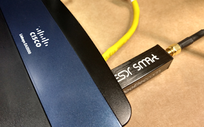
Cisco EA3500 with NooElec RTL-SDR
The video was so interesting, that I found a used EA3500 for sale on ebay and immediately purchased it to try this myself! (not a single one of my routers has a USB interface. Go figure) There are also used ones on amazon as well.

Although it was the topic of SDR caught my attention, it is still a pretty good video on OpenWrt.

The cool thing is that when done - I can move my RTL-SDR device anywhere within range of WiFi! Sweet. No longer limited to USB cable distance of my computer.

For stock firmware, there's no username; default password is admin

You should note that when the router first boots with stock firmware and factory reset, there's NO security on WiFi.

I did this on Windows 10, with the Ubuntu WSL for ssh access and other unix tools like iperf.

My wired test network is setup specifically to allow new devices with the default 192.168.1.1 address to work without having to unplug and re-plug my computer for many devices. However for this exercise I need to connect to OpenWrt before it is configured. So my setup is a little different than the video:


[internet] -- [switch: 192.168.1.x ] --- [yellow ES3500 Internet port]
                                         [blue ES3500 Ethernet port  ] --- [my computer]


While videos are cool, they make for poor reference material for later use. It is difficult to "scroll" though a video looking for a particular technical item. I'll keep track of all the details here.

The first reference is to the WikiDevi Linksys EA3500 page, with a link to the OpenWrt page for the Linksys EA3500. Despite the name factory.bin - this is NOT the stock Linksys software. This is the file to download for OpenWrt. There's more information on the Techdata: Linksys3500 page. That's where you can find a link to Firmware OpenWrt Install URL.

The first thing I did was brick my router. :(  I loaded that openwrt-kirkwood-linksys-audi-squashfs-factory.bin mentioned above. It did not go well. Fortunately there's a magic sequence of events to restore it. Thanks mikemccartney for posting these instructions that worked for me:


1 Plug in the EA3500/4500
2 Power led will blink rapidly
3 Power led will turn off
4 As soon as the power led turns off, unplug the router
5 Wait a few seconds
6 Plug the router back in and repeat the above process

Do that three times, on the fourth time keep the router plugged in and let it boot, hopefully you will now have a functioning router again.

I'm just glad I didn't have to figure out how to JTAG the firmware onto the router.

This time when loading openwrt-kirkwood-linksys-audi-squashfs-factory.bin things went much better.

So back to the video instructions: there's no default web UI when OpenWrt first boots. To initially access the new firmware, use: ssh root@192.168.1.1 and it should look something like this:


0 $ ssh root@192.168.1.1
The authenticity of host '192.168.1.1 (192.168.1.1)' can't be established.
RSA key fingerprint is 6e:6d:a4:4e:83:9e:54:10:b3:be:c0:76:bf:eb:aa:e3.
Are you sure you want to continue connecting (yes/no)? yes
Warning: Permanently added '192.168.1.1' (RSA) to the list of known hosts.


BusyBox v1.24.2 () built-in shell (ash)

  _______                     ________        __
 |       |.-----.-----.-----.|  |  |  |.----.|  |_
 |   -   ||  _  |  -__|     ||  |  |  ||   _||   _|
 |_______||   __|_____|__|__||________||__|  |____|
          |__| W I R E L E S S   F R E E D O M
 -----------------------------------------------------
 DESIGNATED DRIVER (Bleeding Edge, 50107)
 -----------------------------------------------------
  * 2 oz. Orange Juice         Combine all juices in a
  * 2 oz. Pineapple Juice      tall glass filled with
  * 2 oz. Grapefruit Juice     ice, stir well.
  * 2 oz. Cranberry Juice
 -----------------------------------------------------
root@OpenWrt:~#
Next set password with
passwd
command:
root@OpenWrt:~# passwd
Changing password for root
New password:
Retype password:
Password for root changed by root

If you are familar with VI/VIM you can skip this step, otherwise you can install nano:
opkg update

You may wish to save you original configs:
cp  /etc/config/network  /etc/config/network.bak
cp  /etc/config/wireless /etc/config/wireless.bak
Edit /etc/config/network that originally looks like this:
config interface 'loopback'
        option ifname 'lo'
        option proto 'static'
        option ipaddr '127.0.0.1'
        option netmask '255.0.0.0'

config globals 'globals'
        option ula_prefix 'fdbc:cc57:906d::/48'

config interface 'lan'
        option type 'bridge'
        option ifname 'eth0'
        option proto 'static'
        option ipaddr '192.168.1.1'
        option netmask '255.255.255.0'
        option ip6assign '60'

config interface 'wan'
        option ifname 'eth1'
        option proto 'dhcp'

config interface 'wan6'
        option ifname 'eth1'
        option proto 'dhcpv6'

config switch
        option name 'switch0'
        option reset '1'
        option enable_vlan '1'

config switch_vlan
        option device 'switch0'
        option vlan '1'
        option ports '0 1 2 3 5'

config switch_vlan
        option device 'switch0'
        option vlan '2'
        option ports '4 6'

He edits the network from 192.168.1.1 to 192.168.2.1
config interface 'lan'
        option ipaddr '192.168.2.1'
and changes the wan interface from eth1 to wlan0 for both.
config interface 'wan'
        option ifname 'wlan0'

config interface 'wan6'
        option ifname 'wlan0'

Then edit /etc/config/wireless that for a default config, that originally looks like this.
config wifi-device  radio0
        option type     mac80211
        option channel  11
        option hwmode   11g
        option path     'mbus/mbus:pcie-controller/pci0000:00/0000:00:01.0/0000:01:00.0'
        option htmode   HT20
        # REMOVE THIS LINE TO ENABLE WIFI:
        option disabled 1

config wifi-iface
        option device   radio0
        option network  lan
        option mode     ap
        option ssid     OpenWrt
        option encryption none

config wifi-device  radio1
        option type     mac80211
        option channel  36
        option hwmode   11a
        option path     'mbus/mbus:pcie-controller/pci0000:00/0000:00:02.0/0000:02:00.0'
        option htmode   HT20
        # REMOVE THIS LINE TO ENABLE WIFI:
        option disabled 1

config wifi-iface
        option device   radio1
        option network  lan
        option mode     ap
        option ssid     OpenWrt
        option encryption none

Remove the channel selection and enable wifi (by setting disabled to false):
config wifi-device  radio0
        # option channel  11
        option disabled 0
And edit the wifi-iface section for 2GHz:
config wifi-iface
        option device   radio0
        option network  wan
        option mode     sta
        option ssid     yourssid
        option encryption psk2
        option key      yourwifipassword
Edit the wifi-iface section for 5GHz in a similar manner if you have one (I do not). The reboot, wait, and ssh to the NEW IP address:
reboot;exit
# wait...
ssh root@192.168.2.1
Once everything is configured, the cable between the yellow Ethernet port and the switch can be removed, as the router is now a station

[internet] -- [WiFi (same as above switched network)]   
                            [WiFi]  ---- [blue ES3500 Ethernet port  ] --- [my computer]
Other things installed in the video include installing LuCI (the graphical web gui). Note the video installed regular luci; I prefer the luci-ssl, even though the browser will complain that it is not a secure connection (no trusted root for self-signed cert)


opkg update
# opkg install luci # the non-ssl version
opkg install luci-ssl
/etc/init.d/uhttpd start
/etc/init.d/uhttpd enable
Then see which RTL packages are available:
opkg list | grep rtl
He then goes on to install rtl-sdr
opkg install rtl-sdr
which rtl_fm
which rtl_tcp
rtl_tcp -h
Plugging in my NooElec RTL-SDR that I received for Christmas (what a cool gift!!) I see this latest entry with dmesg:
[ 2819.934581] usb 1-1: new high-speed USB device number 2 using orion-ehci
Then simply run rtl_tcp:
root@OpenWrt:~# rtl_tcp
Found 1 device(s):
  0:  Realtek, RTL2838UHIDIR, SN: 00000001

Using device 0: Generic RTL2832U OEM
Found Rafael Micro R820T tuner
[R82XX] PLL not locked!
Tuned to 100000000 Hz.
listening...
Use the device argument 'rtl_tcp=127.0.0.1:1234' in OsmoSDR (gr-osmosdr) source
to receive samples in GRC and control rtl_tcp parameters (frequency, gain, ...).
Other things installs in the video:

 
opkg list | grep dump
opkg install dump1090
opkg install iperf
Part two of the video starts out a bit confusing... but skip the first 7 minutes and pick up at the OpenWrt login prompt. There's a reminder on restarting WiFi:

wifi down; wifi up
# or
ifconfig wlan0 down
ifconfig wlan0 up

Basically to ensure there's an IP address listed for wlan0. (the client DHCP address for your WiFi network; remember this device was configured as STA, not AP (above).
As such, the ES3500 is connected to the "internet" via WiFi instead of via the yellow RJ-45 connector. Thus for wireless access, port forwarding is needed. At first, I setup a simple traffic rule that worked:


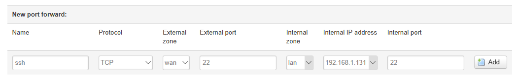
However I wanted to follow along and use port forwarding instead, like this:

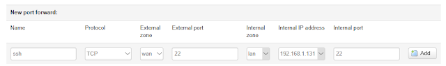
A port forward that looks like it should work, but does not.

Unfortunately, the video already had many of the port forwards already configured. I had a difficult time with getting ssh working. I kept getting these odd connection refused errors:
gojimmypi@ElectronicsDesk : ~
255 $ ssh root@192.168.1.131
ssh: connect to host 192.168.1.131 port 22: Connection refused
Now "connection refused" is an interesting error. It says things are working but being rejected. I was sure I had it configured correctly. As it turns out there's a feature specifically to allow ssh under System - Administration:


Even setting the "allow remote hosts", I continued to get the port refusal error. So in the video, he connects to the client STA address of the EA3500. Yet when on the local 192.168.2.x network, I was ssh'ing into the router IP address: 192.168.2.1 and not its client STA address of 192.168.1.131 - so I used that as a port forward instead. Note that it shows up in the drop-down as "(Openwrt,lan)" next to the IP addy


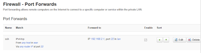
And so once that is working, several other ports also need to be forwarded:

Note that when moving your client computer between the ES3500 network (192.168.2.x) and the local wired/wireless network (192.168.1.x) - there's a delay of up to several minutes in Windows obtaining the new address and getting everything setup, during which you'll see messages like this when attempting ssh:


ssh: connect to host 192.168.1.131 port 22: Software caused connection abort
ssh: connect to host 192.168.1.131 port 22: Resource temporarily unavailable
ssh: connect to host 192.168.1.131 port 22: Network is unreachable

If you still have problems connecting, recheck settings and try reboot. But be patient, it does take some time. Again, note that I believe the port forwards in the video are completely wrong - and the only reason he was able to get it working was the traffic rules. I have no traffic rules - just the port forwards, but to a different address. But then again, I spent the better part of the afternoon playing with this - and the video author sped though the entire process in an impressive 37 minutes apparently with no editing / interruptions. Impressive.
Once that is working, I setup iperf as a server on the EA3500:
iperf -s
In a separate shell, staying local the PC (I also needed to install iperf):
sudo apt-get install iperf
iperf -c 192.168.1.131 -i 3 -t 30
and saw mediocre performance from this "gigabit" router:

------------------------------------------------------------
Client connecting to 192.168.1.131, TCP port 5001
TCP window size:  512 KByte (default)
------------------------------------------------------------
[  3] local 192.168.1.143 port 5607 connected with 192.168.1.131 port 5001
[ ID] Interval       Transfer     Bandwidth
[  3]  0.0- 3.0 sec  6.75 MBytes  18.9 Mbits/sec
[  3]  3.0- 6.0 sec  8.00 MBytes  22.4 Mbits/sec
[  3]  6.0- 9.0 sec  7.12 MBytes  19.9 Mbits/sec
[  3]  9.0-12.0 sec  7.75 MBytes  21.7 Mbits/sec
[  3] 12.0-15.0 sec  7.38 MBytes  20.6 Mbits/sec
[  3] 15.0-18.0 sec  7.25 MBytes  20.3 Mbits/sec
[  3] 18.0-21.0 sec  7.88 MBytes  22.0 Mbits/sec
[  3] 21.0-24.0 sec  7.62 MBytes  21.3 Mbits/sec
[  3] 24.0-27.0 sec  7.75 MBytes  21.7 Mbits/sec
[  3] 27.0-30.0 sec  7.88 MBytes  22.0 Mbits/sec
[  3]  0.0-30.1 sec  75.5 MBytes  21.1 Mbits/sec
Note that Norton Antivirus popped up and warned about the iperf traffic; the default recommended action was to block it. Your AV may simply quietly block it. So if ssh and the web interface are working but not iperf; check your antivirus software. YMMV.

The video moves on to trying performance with a 5GHz band. I don't have any other 5GHz routers, so I could not test this. Important thing to note is that he ended up apparently needed to power cycle the router when changing from 2.5GHx to 5GHz.

So on to SDR "Sharp" (which was also already install in the video). You can download the AirSpy SDR# here. Norton AV gave me a ton of grief on many of the SDR# executables. Here's the config in SDR#. The only thing is setting the IP address for RTL-SDR (tcp):


Although the original pic above has the RTL-SDR plugged directly into the router, it is probably a good idea to use an extension cord, as shown in the video to get the receiver a bit farther away.

Note that we are port forwarding the br-lan address: 192.168.2.1 from the 192.168.1.x network. Thus we need to tell rtl_tcp to listen on that address:

rtl_tcp -a 192.168.2.1 -f 95300000
Press play button in SDR# and voila!


Resources, Inspiration, Credits, and Other Links:


Sunday, July 16, 2017

Updating adafruit.io ESP8266 MQTT code

While working on my flow and pressure project, I stumbled upon a notice that Adafruit planned to change the SSL info for adafruit.io. I had been using this (beta) site for mqtt telemetry. And so today... sure enough: my code is broken & no longer connecting.


I was hoping it was a simple matter of updating the SSL fingerprint to a new value.

const char* fingerprint = "26 96 1C 2A 51 07 FD 15 80 96 93 AE F7 32 CE B9 0D 01 55 C4";
No luck there, as the fingerprint did not change - but the declarative name did. <sigh> Well, so the github repository is here. But I have been blissfully ignorant of exactly where everything is stored. A mixed blessing in allowing me focusing on my code, but sometimes scary in not knowing how everything works. Alas no-one can know everything. So back to the ESP8266 crutch: The Arduino IDE! Click Sketch - Include Library - Manage Libraries. (it is the top-most menu item). Find the installed adafruit mqtt library and click update!


If like me - you are using VisualMicro, I believe it is usually best to exit and restart Visual Studio.


It didn't work. Not only does the connection still fail, but the needed code was apparently not actually updated (the drawback of hiding libraries in a GUI). I know it is not working as the new fingerprint is defined with AIO_SSL_FINGERPRINT and the old one with fingerprint, and there's no compile error without the AIO_SSL_FINGERPRINT. So ya, there appears to be a new include file: adafruitio_definition. I have no such file on my entire system. Well, seems that the Arduino IDE was not successful in getting the really latest adafruit mqtt library.
So the issue here is more than the MQTT library... I also needed to update the Adafruit Arduino IO (listed immediately above in the screen snip). Again exit / restart Visual Studio.

Next, I saw this error:
AdafruitIO.h: 22:31: fatal error: ArduinoHttpClient.h: No such file or directory
   #include "ArduinoHttpClient.h"
   compilation terminated
Seems that the latest Adafruit MQTT also needs the new (apparently experimental at this time) ArduinoHttpClient library. So I installed that from Arduino IDE as well. And restarted Visual Studio. So ya, just as described here. (once you kow that the Arduino IO library is required by new new MQTT.

Ok, so now what? The github repository sample code for adafruitio secure esp8266 is still from last year. No tweets from adafruitio. No other messages on the forum. Blog apparently has "major outage".


End of story for today on this topic. Hopefully more documentation and examples will be available soon.

Saturday, July 15, 2017

ESP8266 OTA Water Pressure Flow Monitor

I've been working with the ESP8266 for quite some time now, but I've only programmed it while it was sitting right at my desk and having it plugged into a USB port. A variety of projects that I have developed have always been convenient to test. However my latest creation involves water. I could not quite imagine how I'd test this at my workbench, nor did it seem very appealing to be programming in the garage. In the summer. In California.

Today I discovered how amazingly simply it is to do "Over The Air" (OTA) programming of the ESP8266, thanks to this really cool Random Nerd Tutorial - ESP8266 OTA Updates with Arduino IDE | Over the Air.

I've been wanting to hook up these pressure and flow sensors that I found on ebay to monitor water usage. I also needed a few fittings that I found on Amazon. I purchased there as I could return them free, no hassle if there was a problem; I had a dreadful time finding anything like this at the local hardware store. I needed this Stainless Steel 316 Cast Pipe Fitting, Hex Bushing, MSS SP-114, 3/4" X 1/4" NPT Male X Female adapter for the pressure sensor, and thisStainless Steel 316 Cast Pipe Fitting, Tee, Class 150, 3/4" NPT Female so that I could hook up both the pressure sensor and flow meter at the same time. The result is a male-female connector that I can slip inline.


You may wonder why I would be interested in something as boring as water pressure. Well, not long ago I discovered my pressure regulator quietly failed. Let's just say I will never again ignore water pressure! There's a reason for the regulator - and the maximum ratings on the water heater. The water softener. The reverse osmosis system.... For only about 10 bucks, you can keep an eye on pressure the  manual, old-school way with this Rain Bird P2A Water Pressure Test Gauge - but what fun is that when there's an electronic gizmo option?

I admit I had some temporary disappointment at the beginning of Step 3 of the OTA tutorial, where I expected to see the the esp8266-xxxxxx at my_esp_ip_address port. I did not. I was not able to see this until exiting and restarting Arduino. No worries, onward!

The next step is to program in some other environment other than the Arduino IDE. I am quite addicted to Visual Studio. I have both the VisualGDB and VisualMicro add-ins. I like VisualMicro in that I can take Arduino code samples and immediately start coding. I have yet to figure out how to do this with VisualGDB. The last time I asked about it, there was no hope on the horizon for Arduino support in VisualGDB,

Initially, it appears there's no option other than the Arduino IDE to actually program OTA. I could find nothing in Visual Studio where it could "see" the pseudo-serial-over-ethernet port. Ha! But fortunately there's a verbose output from the Arduino IDE. In particular this last command shown before uploading:

python.exe C:\Users\gojimmypi\AppData\Local\Arduino15\packages\esp8266\hardware\esp8266\2.3.0/tools/espota.py -i 192.168.1.103 -p 8266 --auth= -f C:\Users\GOJIMM~1\AppData\Local\Temp\arduino_build_690448/sketch_jul15a.ino.bin

The important thing here is that there's a python script called espota.py that sends a binary file to the OTA client. (side note: simply genius implementation in less than 9K!) The paths are crazy long, but the command is essentially this:

python.exe espota.py -i 192.168.1.101 -p 8266 --auth= -f yourfile.bin
Pasting the same OTA sample code into a VisualMicro Ardino Project in Visual Studio... then compiling, shows the output path of the binary:
"C:\Users\gojimmypi\AppData\Local\arduino15\packages\esp8266\tools\esptool\0.4.9/esptool.exe" -eo "C:\Users\gojimmypi\AppData\Local\arduino15\packages\esp8266\hardware\esp8266\2.3.0/bootloaders/eboot/eboot.elf" -bo "C:\Users\gojimmypi\AppData\Local\Temp\VMBuilds\WaterPressureFlow\esp8266_generic\Release/WaterPressureFlow.ino.bin" -bm qio -bf 40 -bz 4M -bs .text -bp 4096 -ec -eo "C:\Users\gojimmypi\AppData\Local\Temp\VMBuilds\WaterPressureFlow\esp8266_generic\Release/WaterPressureFlow.ino.elf" -bs .irom0.text -bs .text -bs .data -bs .rodata -bc -ec
This one is an even longer and crazier command. Really the only thing we are interested in is where the output file is stored. In my case it is:
"C:\Users\gojimmypi\AppData\Local\Temp\VMBuilds\WaterPressureFlow\esp8266_generic\Release/WaterPressureFlow.ino.bin"
There's some sloppy use of mixing forward and back-slashes; for Windows I highly recommend editing them and making them all backslashes.

So now using the Arduino OTA command with the destination of the VisualStudio binary, we can develop OTA with Visual Studio! My command looks like this:
python.exe C:\Users\gojimmypi\AppData\Local\Arduino15\packages\esp8266\hardware\esp8266\2.3.0\tools\espota.py -i 192.168.1.103 -p 8266 --auth= -f C:\Users\gojimmypi\AppData\Local\Temp\VMBuilds\WaterPressureFlow\esp8266_generic\Release\WaterPressureFlow.ino.bin
I thought perhaps this could be fully automated by adding the command to the Post Build Event in VisualStudio:
 
However I was unable to get the command to trigger. This article on Specifying Build Events at Microsoft seems to indicate that last option "In Excluded From Build, specify Yes if you do not want the event to run". However my prompt is "Use in Build". I tried both Yes and No - and the OTA command appears to never have been attempted. Perhaps this is because it is a VisualMicro project. No worries, still just as easy to use the up-arrow in a DOS box to re-upload freshly compiled code.

I'm still hopeful that I will be able to do this in a single build operation. The VisualMicro site has a page indicating that build events are now supported. I've submitted a question to their support forum to find out. It appears the only option is a "quite convoluted and difficult to test" option. Hopefully they have the built-in events working.
And indeed YES! Just minutes after posting my question on the forum, I received a response! A simple matter of right-click on project - add - Add Local Board.txt with this text

# WaterPressureFlow build property overrides
#
# local project board.txt overrides
network.port=8266
as described here. So no need for a convoluted solution or manual specification of build event. It just works! Be sure to press "enter" when entering an IP address for serial port (otherwise it won't stick). Now the VisualMicro "Build & Upload" sends OTA data. Sweet. :)


See also: https://github.com/gojimmypi/mqttFlowESP8266 and Updating adafruit.io ESP8266 MQTT code


Find gojimmypi at gojimmypi.github.io

I'm currently working on my new blog home at  gojimmypi.github.io After implementing a variety of features such as dark mode , syntax hi...