Showing posts with label JTAG. Show all posts

Tuesday, February 12, 2019

ULX3S - ujprog on Windows WSL or MingGW

I continue to learn about my latest gizmo that arrived all the way from Croatia - the ULXS3. (see my prior blog)

TL;DR; @emard has precompiled binaries. Otherwise compile your own ujprog using apt-get install mingw-w64. A specific makefile is needed to use the new compiler. The current f32c repo has a very old 32-bit ftd2xx.lib; the updated 64 bit version will typically be needed on modern machines. New drivers are here. The ujprog and OpenOCD for ULX3S cannot be used concurrently (FTDI vs libusbK drivers). See the ujprog README that I created.

I've been trying to use WSL for FPGA development. I'm primarily a Windows developer for the Day Job. I like the Windows tools - particularly Visual Studio and VS Code. I also simply think WSL is really cool. (see also WSL on GitHub)

As a reminder, do not modify WSL filesystem file from Windows! Yes, I've seen some pretty weird things happen when I tested that. But feel free to edit any other files. For instance, the entire C:\ directory is available in WSL as /mnt/c/.

Note that similar to the TinyFPGA setup script, I also created a ULXS3 Setup Script.

One of the problems with WSL is the lack of native USB support (glaring omission, I know). So I wanted to see if the ujprog JTAG programmer could be used from Windows. Not super cool having a disjointed environment. For example, when creating the ujprog in WSL:
git clone https://github.com/f32c/tools.git f32c_tools
cp Makefile.linux Makefile
make
./ujprog -t
I see this result:

$ ./ujprog -t
ULX2S / ULX3S JTAG programmer v 3.0.92 (built Feb 12 2019 10:14:16)
Cannot find JTAG cable.

If compiling ujprog for Windows (yes, I admit I tried to type make at a DOS prompt - lol!), install MinGW (I downloaded mine from here; the downloads link however points here). See the wiki: HOWTO Install the MinGW GCC Compiler Suite.


Press "Continue" and upon completion:


Then the MinGW install manager runs:


I chose these options:


Then click "Installation - Apply Changes"


When finished, there should be an indication that "all changes applied successfully"


From Windows, run:

C:\MinGW\msys\1.0\msys.bat


The MINGW32 home directory (from the Windows perspective) will be: C:\MinGW\msys\1.0\home\{your user name}

Unlike other bash prompts, this one does not seem to map the entire C:\ drive, so I re-cloned the repo to my home/workspace directory in MinGW32:

mkdir workspace
cd workspace
git clone https://github.com/f32c/tools.git f32c_tools

Try to compile the linux make file:

cp Makefile.linux Makefile
make

of course results in failure:

$ make
cc -Wall -D__linux__  -static ujprog.c /usr/lib/`uname -m`-linux-gnu/libftdi.a /usr/lib/`uname -m`-linux-gnu/libusb.a -o ujprog
/bin/sh: cc: command not found
make: *** [ujprog] Error 127

Try to compile the win make file (copy the respective Makefile so the -f is not needed every time):

cp Makefile.win Makefile
make

results in a bunch of warnings repeated about usleep, but more importantly a critical error: 'EOPNOTSUPP' undeclared as shown here:

In file included from ujprog.c:55:
[... snip ...]
c:\mingw\include\unistd.h:100:29: note: declared here
 int __cdecl __MINGW_NOTHROW usleep( useconds_t )__MINGW_ATTRIB_DEPRECATED;
                             ^~~~~~
ujprog.c: In function 'shutdown_usb':
ujprog.c:621:2: warning: 'usleep' is deprecated [-Wdeprecated-declarations]
  ms_sleep(10);
  ^~~~~~~~
In file included from ujprog.c:55:
c:\mingw\include\unistd.h:100:29: note: declared here
 int __cdecl __MINGW_NOTHROW usleep( useconds_t )__MINGW_ATTRIB_DEPRECATED;
                             ^~~~~~
ujprog.c: In function 'exec_svf_tokenized':
ujprog.c:1488:9: error: 'EOPNOTSUPP' undeclared (first use in this function); did you mean 'WSAEOPNOTSUPP'?
   res = EOPNOTSUPP;
         ^~~~~~~~~~
         WSAEOPNOTSUPP
ujprog.c:1488:9: note: each undeclared identifier is reported only once for each function it appears in
ujprog.c: In function 'async_read_block':
ujprog.c:2788:4: warning: 'usleep' is deprecated [-Wdeprecated-declarations]
    ms_sleep(backoff * 4);
    ^~~~~~~~
In file included from ujprog.c:55:
[... snip ...]
I tried making the changes described in nmap/nmap#183 - specifically adding to ujprog.c:

#undef EOPNOTSUPP
#define EOPNOTSUPP      WSAEOPNOTSUPP  /* Operation not supported */

And Voila! Success! ujprog.exe for Windows! I created issue this f32c/tools/#8 and this PR f32c/tools#9 to help others that may encounter this problem.

I'm not sure this PR will be accepted, as the root cause may be:
 probably including a wrong errno.h
When running ujprog.exe (from either MinGW32 bash prompt, or DOS command prompt):

ULX2S / ULX3S JTAG programmer v 3.0.92 (built Feb 10 2019 15:25:08)
Usage: ujprog [option(s)] [bitstream_file]

 Valid options:
  -p PORT       Select USB JTAG / UART PORT (default is 0)
  -P COM        Select COM port (valid only with -t or -a)
  -j TARGET     Select bitstream TARGET as SRAM (default) or FLASH (XP2 only)
  -f ADDR       Start writing to SPI flash at ADDR, optional with -j flash
  -s FILE       Convert bitstream to SVF FILE and exit
  -r            Reload FPGA configuration from internal Flash (XP2 only)
  -t            Enter terminal emulation mode after completing JTAG operations
  -b SPEED      Set baudrate to SPEED (300 to 3000000 bauds)
  -e FILE       Send and execute a f32c (MIPS/RISCV) binary FILE
  -x SPEED      Set binary transfer speed, optional with -e
  -a FILE       Send a raw FILE
  -d            debug (verbose)
  -D DELAY      Delay transmission of each byte by DELAY ms
  -q            Suppress messages

This seemed to be a convoluted solution (hm. as always). So a bit of googling and I found a stackoverflow regarding using MinGW for Ubuntu. Something a little more direct from WSL:
sudo apt-get install mingw-w64
It is however, massive, at nearly 750 MB:
Reading package lists... Done
Building dependency tree
Reading state information... Done
The following additional packages will be installed:
  binutils-mingw-w64-i686 binutils-mingw-w64-x86-64 g++-mingw-w64 g++-mingw-w64-i686 g++-mingw-w64-x86-64
  gcc-mingw-w64 gcc-mingw-w64-base gcc-mingw-w64-i686 gcc-mingw-w64-x86-64 mingw-w64-common mingw-w64-i686-dev
  mingw-w64-x86-64-dev
Suggested packages:
  gcc-7-locales wine wine64
The following NEW packages will be installed:
  binutils-mingw-w64-i686 binutils-mingw-w64-x86-64 g++-mingw-w64 g++-mingw-w64-i686 g++-mingw-w64-x86-64
  gcc-mingw-w64 gcc-mingw-w64-base gcc-mingw-w64-i686 gcc-mingw-w64-x86-64 mingw-w64 mingw-w64-common
  mingw-w64-i686-dev mingw-w64-x86-64-dev
0 upgraded, 13 newly installed, 0 to remove and 1 not upgraded.
Need to get 127 MB of archives.
After this operation, 744 MB of additional disk space will be used.
So after the install, a quick compile resulted in:
gcc.exe -c ujprog.c -o ujprog.o -I.
make: gcc.exe: Command not found
Makefile:29: recipe for target 'ujprog.o' failed
make: *** [ujprog.o] Error 127
Ah yes, of course. The Makefile needs to be adjusted to use the new mingw compiler (I added to my PR, suggesting to include a new Makefile.ming32_64:
# Project: ujprog

CPP  = x86_64-w64-mingw32-gcc
CC   = x86_64-w64-mingw32-gcc
WINDRES = windres.exe
RES  =
OBJ  = ujprog.o $(RES)
LINKOBJ  = ujprog.o $(RES)
LIBS = -s -static -L. -lftd2xx
INCS = -I.
CXXINCS = -I.
BIN  = ujprog.exe
CXXFLAGS = $(CXXINCS) -wAll
CFLAGS = $(INCS)
RM = rm -f

.PHONY: all all-before all-after clean clean-custom

all: all-before ujprog.exe all-after


clean: clean-custom
        ${RM} $(OBJ) $(BIN)

$(BIN): $(OBJ)
        $(CC) $(LINKOBJ) -lftd2xx -o "ujprog.exe" $(LIBS)

ujprog.o: ujprog.c
        $(CC) -c ujprog.c -o ujprog.o $(CFLAGS)

The next problem was the ftd2xx.lib file was meant for Linux not Windows, 32 bit not 64 bit .

$ make
x86_64-w64-mingw32-gcc -c ujprog.c -o ujprog.o -I.
x86_64-w64-mingw32-gcc ujprog.o  -lftd2xx -o "ujprog.exe" -s -static -L. -lftd2xx
/usr/bin/x86_64-w64-mingw32-ld: skipping incompatible ./ftd2xx.lib when searching for -lftd2xx
/usr/bin/x86_64-w64-mingw32-ld: cannot find -lftd2xx
/usr/bin/x86_64-w64-mingw32-ld: skipping incompatible ./ftd2xx.lib when searching for -lftd2xx
/usr/bin/x86_64-w64-mingw32-ld: cannot find -lftd2xx
collect2: error: ld returned 1 exit status
Makefile:26: recipe for target 'ujprog.exe' failed
make: *** [ujprog.exe] Error 1
Searching my entire drive, I found the Windows DLL version in my C:\downloads\FTDI directory. Specifically from the WSL perspective:
cd ~/workspace/f32c_tools/ujprog
cp '/mnt/c/download/FTDI/CDM v2.12.28 WHQL Certified/amd64/ftd2xx.lib' ./ftd2xx.lib
make clean
make
This successfully compiled the Windows exe, leaving the file in the Windows-equivalent of my Ubuntu directory:
C:\Users\gojimmypi\AppData\Local\Packages\CanonicalGroupLimited.UbuntuonWindows_79rhkp1fndgsc\LocalState\rootfs\home\gojimmypi\workspace\f32c_tools\ujprog
Sadly, I received the same error in Windows as I did in WSL:
ULX2S / ULX3S JTAG programmer v 3.0.92 (built Feb 12 2019 17:48:54)
FT_Open() failed
Cannot find JTAG cable.
I later discovered this problem was a Windows device driver conflict. In my prior blog, I got OpenOCD working. It uses the libusbK drivers. However, ujprog.exe uses the FTDI drivers. Changing the Windows drivers back to FTDI allows the freshly compiled app to work from Windows!

Now on to getting more serious by uploading my own FPGA and ESP32 code. I'll need to be super sure I can get back to "as shipped" FPGA image, otherwise I may not be able to program the ESP32 since it is not connected directly to any of the exposed pins, rather only the FPGA (same with the SPI display). Thus a passthru app is needed:
Yes, if ESP32 needs FPGA as bypass logic to OLED. If you need ESP32 to write to OLED while FPGA is running user defined core then those few OLED bypass signals must be copy pasted from passthru source to user's source. It's makes very small LUT usage.
--@emard
More info coming soon!

Resources, Inspiration, Credits, and Other Links:

Saturday, February 9, 2019

ULX3S - Day 1

I first learned about the ULX3S via the Hackaday Article last month. (see also hackster.io) There was an offer for boards at the bottom of the radiona.org ulx3s page, so I promptly contacted them. There was only one 12F board left (I confirmed mine is the latest v3.0.3 version), and without the ESP32 connected. Goran was so kind: he not only soldered on the ESP32, but he also included a sticker, headers, the SPI display, and even an awesome 3D-Printed case! (for those that follow me - you know my ongoing quest to find good enclosures for projects)

My board arrived all the way from Croatia, and just in time for the weekend! Power-on success is always a good start:


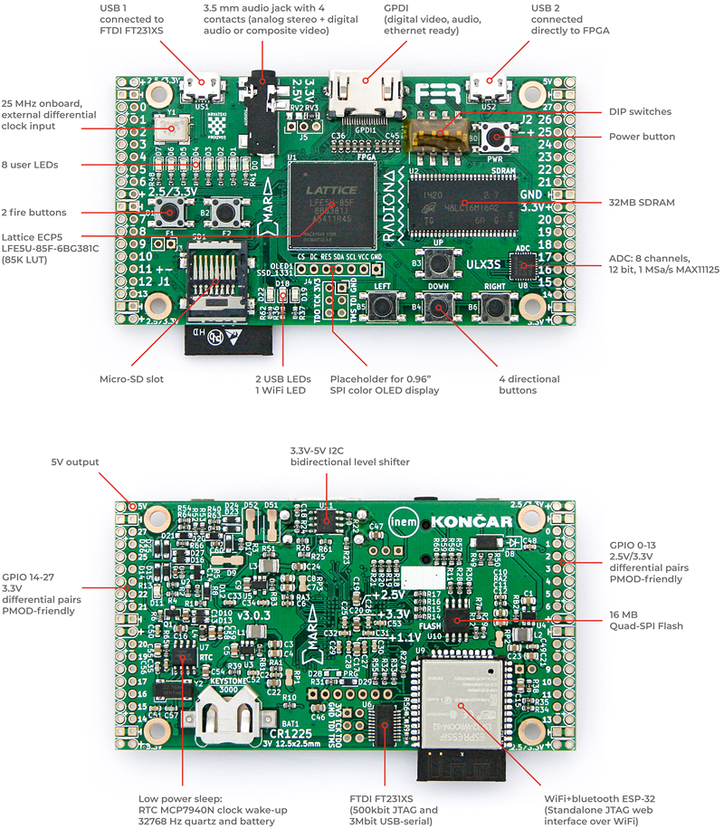
One of the first things I noticed is that there are TWO micro-USB ports:

ULX3S Board Diagram, from http://radiona.org/ulx3s/
One of them is used for JTAG, connected to a  FTDI FT231XS chip. The other is "connected directly to FPGA". Despite having reviewed the online documentation prior to board arrival, I admit I was surprised to see the two USB connectors. (Uh-oh; which do I use?? will there be ground-loop problem if I use them both?) The feature list only names the one used for JTAG, but both are of course clearly labeled on the diagram (see above); Interesting how one sees things differently when actually holding the physical item.

There are a bunch of interesting links for the ulx3s here.

I received a suggestion that I should first test board with this repo: github.com/emard/ulx3s-bin

There's some information on using JTAG with the ULX3S here: github.com/emard/ulx3s-bin.

My board came with what appeared to be a preloaded WiFi AP (source code should be this one). Goran also suggested that:
for using web interface you will need passthru sample; with ujprog you will program this file and you use -j FLASH option:
ujprog -j FLASH passthru_ulx3s_v20_12k.bit
then power off board. Power on with SD card with config file and it will connect to your network then you can use web interface to upload sram.svf files to SD card and program then from WEB interface or use buttons and OLED.

(I didn't actually do this yet)

To use the WiFi AP, a file called ulx3s-wifi.conf should be placed on a fat32 formated SD card:
{
  "host_name": "ULX3S",
  "ssid": "MyMagicSSID",
  "password": "WiFiPassWord8675309",
  "http_username": "user",
  "http_password": "pass"
}

I installed an 8GB SD card that I had used for a Raspberry Pi (I left all the RPi files) - but it did not seem to be used when I connected to the ESP32 AP. I was unable to connect with Windows 10. It seemed to see there was a "problem" in that there was no internet connectivity (duh). I had more success with my phone, connecting to the address shown on the SPI display:  http://192.168.1.4.1/  - however I was not prompted for a WiFi password, nor a username / password. I suspect somehow the SD card was not detected / not used.

The tools include a forked version of OpenOCD (oddly, no PR's accepted, no ability to open issues). Heads up that some fetches are from https://repo.or.cz/ (not sure why everything is not hosted on GitHub, this certainly makes PR's a bit less convenient - but no issue if not accepted anyhow). I built mine for some JTAG devices I had on hand, as I was not sure what "auto" meant (install if found? install everything?).
sudo apt-get install make libtool pkg-config autoconf automake texinfo libusb-1.0-0-dev
git clone https://github.com/emard/openocd.git ulx32_OpenOCD
cd ulx32_OpenOCD
./bootstrap 
./configure --prefix=/home/$USER/workspace --enable-ftdi --enable-ft232r --enable-stlink  --enable-usb-blaster --enable-jlink  --enable-buspirate
make
sudo make install
So ok, that didn't initially work for me. I ended up with this "error: libusb-1.x is required for the MPSSE mode of FTDI based devices" message:
...
checking whether to build a release... no
checking whether to build Doxygen as HTML... yes
checking whether to build Doxygen as PDF... no
checking whether to enable verbose JTAG I/O messages... no
checking whether to enable verbose USB I/O messages... no
checking whether to enable verbose USB communication messages... no
checking whether to enable malloc free space logging... no
checking whether to enable ZY1000 minidriver... no
checking whether to enable dummy minidriver... no
checking whether standard drivers can be built... yes
checking for LIBUSB1... no
configure: WARNING: libusb-1.x not found, trying legacy libusb-0.1 as a fallback; consider installing libusb-1.x insteadchecking for LIBUSB0... yes
checking for HIDAPI... no
checking for LIBFTDI... no
checking for LIBFTDI... yes
checking for LIBJAYLINK... no
configure: error: libusb-1.x is required for the MPSSE mode of FTDI based devices
The solution was to install libusb-1.0-0-dev. (added, above to apt-get install; many thanks to daveshah1 for that tip) Afterwards, all was well:

Enabled transports:
 - USB ............................ yes
 - TCP ............................ yes


OpenOCD configuration summary
--------------------------------------------------
MPSSE mode of FTDI based devices        yes
ST-Link JTAG Programmer                 yes
TI ICDI JTAG Programmer                 yes (auto)
Keil ULINK JTAG Programmer              yes (auto)
Altera USB-Blaster II Compatible        yes (auto)
Bitbang mode of FT232R based devices    yes
Versaloon-Link JTAG Programmer          yes (auto)
TI XDS110 Debug Probe                   yes (auto)
OSBDM (JTAG only) Programmer            yes (auto)
eStick/opendous JTAG Programmer         yes (auto)
Andes JTAG Programmer                   yes (auto)
USBProg JTAG Programmer                 yes (auto)
Raisonance RLink JTAG Programmer        yes (auto)
Olimex ARM-JTAG-EW Programmer           yes (auto)
CMSIS-DAP Compliant Debugger            no
Cypress KitProg Programmer              no
Altera USB-Blaster Compatible           yes
ASIX Presto Adapter                     yes (auto)
OpenJTAG Adapter                        yes (auto)
SEGGER J-Link Programmer                yes

Despite the instructions, @emard commented on gitter:
Don't use my openocd, it's obsolete (I should remove). Use latest mainstream OpenOCD, they included my patch 
That fork of OpenOCD was from github.com/ntfreak/openocd

Unfortunately, I was once again reminded that USB devices are not supported on WSL. For instance:
$ lsusb -t
/sys/bus/usb/devices: No such file or directory
Although I was able to get around this with the TinyFPGA that could use either USB or TTY drivers, OpenOCD does not. It uses only USB drivers. So I ended up downloading a pre-built binary for OpenOCD on Windows. That didn't initially work either - as the default drivers that Windows installed were the FTDI ones:


As the error appeared that OpenOCD was looking for the libusb drivers:
GNU MCU Eclipse 64-bit Open On-Chip Debugger 0.10.0+dev-00462-gdd1d90111 (2019-01-18-11:42)
Licensed under GNU GPL v2
For bug reports, read
        http://openocd.org/doc/doxygen/bugs.html
Info : only one transport option; autoselect 'jtag'
FT232R num: TCK = 5 DSR
FT232R num: TMS = 6 DCD
FT232R num: TDI = 7 RI
FT232R num: TDO = 3 CTS
FT232R num: TRST = 2 RTS
FT232R num: SRST = 4 DTR
adapter speed: 1000 kHz
Error: libusb_open() failed with LIBUSB_ERROR_NOT_SUPPORTED
Error: ft232r not found: vid=0403, pid=6015, serial=[any]
Zadig to the rescue once again, forcing a change to the drivers to libusbK:

This worked! OpenOCD found the Lattice FPGA:
GNU MCU Eclipse 64-bit Open On-Chip Debugger 0.10.0+dev-00462-gdd1d90111 (2019-01-18-11:42)
Licensed under GNU GPL v2
For bug reports, read
        http://openocd.org/doc/doxygen/bugs.html
Info : only one transport option; autoselect 'jtag'
FT232R num: TCK = 5 DSR
FT232R num: TMS = 6 DCD
FT232R num: TDI = 7 RI
FT232R num: TDO = 3 CTS
FT232R num: TRST = 2 RTS
FT232R num: SRST = 4 DTR
adapter speed: 1000 kHz
Info : clock speed 1000 kHz
Info : JTAG tap: lfe5u12.tap tap/device found: 0x21111043 (mfg: 0x021 (Lattice Semi.), part: 0x1111, ver: 0x2)
Warn : gdb services need one or more targets defined
   TapName             Enabled  IdCode     Expected   IrLen IrCap IrMask
-- ------------------- -------- ---------- ---------- ----- ----- ------
 0 lfe5u12.tap            Y     0x21111043 0x21111043     8 0x05  0xff
open("bitstream.svf"): No such file or directory
svf svf [-tap device.tap]  [quiet] [nil] [progress] [ignore_error]
xsvf (tapname|'plain') filename ['virt2'] ['quiet']
I ran OpenOCD like this, as decribed in the docs:
openocd.exe --file=ft231x.ocd --file=ecp5-XXf.cfg
with the contents of ft231x.ocd:
interface ft232r
ft232r_vid_pid 0x0403 0x6015
# ULX3S specific GPIO setting
ft232r_tck_num DSR
ft232r_tms_num DCD
ft232r_tdi_num RI
ft232r_tdo_num CTS
# trst/srst are not used but must have different values than above
ft232r_trst_num RTS
ft232r_srst_num DTR
adapter_khz 1000
and ecp5-XXf.cfg:

telnet_port 4444
gdb_port 3333

# JTAG TAPs
jtag newtap lfe5u12 tap -expected-id 0x21111043 -irlen 8 -irmask 0xFF -ircapture 0x5
#jtag newtap lfe5u25 tap -expected-id 0x41111043 -irlen 8 -irmask 0xFF -ircapture 0x5
#jtag newtap lfe5u45 tap -expected-id 0x41112043 -irlen 8 -irmask 0xFF -ircapture 0x5
#jtag newtap lfe5u85 tap -expected-id 0x41113043 -irlen 8 -irmask 0xFF -ircapture 0x5

init
scan_chain
svf -tap lfe5u12.tap -quiet -progress bitstream.svf
shutdown


 Make the ujprog (ULX2S / ULX3S JTAG programmer)
git clone https://github.com/f32c/tools.git f32c_tools
cd f32c_tools/ujprog
cp Makefile.linux Makefile
make

Usage for ujprog programmer:
ULX2S / ULX3S JTAG programmer v 3.0.92 (built Feb  8 2019 15:32:33)
Usage: ujprog [option(s)] [bitstream_file]

 Valid options:
  -p PORT       Select USB JTAG / UART PORT (default is 0)
  -P TTY        Select TTY port (valid only with -t or -a)
  -j TARGET     Select bitstream TARGET as SRAM (default) or FLASH (XP2 only)
  -f ADDR       Start writing to SPI flash at ADDR, optional with -j flash
  -s FILE       Convert bitstream to SVF FILE and exit
  -r            Reload FPGA configuration from internal Flash (XP2 only)
  -t            Enter terminal emulation mode after completing JTAG operations
  -b SPEED      Set baudrate to SPEED (300 to 3000000 bauds)
  -e FILE       Send and execute a f32c (MIPS/RISCV) binary FILE
  -x SPEED      Set binary transfer speed, optional with -e
  -a FILE       Send a raw FILE
  -d            debug (verbose)
  -D DELAY      Delay transmission of each byte by DELAY ms
  -q            Suppress messages

Make the ftx-prog programmer:
git clone https://github.com/richardeoin/ftx-prog.git
cd ftx-prog
make

Usage for ftx-prog:
ftx_prog: version 0.2
Modified for the FT-X series by Richard Meadows

Based upon:
ft232r_prog: version 1.23, by Mark Lord.

Usage:  ftx_prog [ ]..

where  must be any of:
    --help                                  # (show this help text)
    --dump                                  # (dump eeprom settings to stdout)
    --verbose                               # (show debug info and raw eeprom contents)
    --save                       <file>     # (save original eeprom contents to file)
    --restore                    <file>     # (restore initial eeprom contents from file)
    --8bit-strings                        # (byte strings)
    --cbus  [1..7]  [Tristate|RxLED|TxLED|TxRxLED|PWREN|SLEEP|Drive_0|Drive_1|GPIO|TXDEN|CLK24MHz|CLK12MHz|CLK6MHz|BCD_Charger|BCD_Charger#|I2C_TXE|I2C_RXF|VBUS_Sense|BitBang_WR|BitBang_RD|Time_Stamp|Keep_Awake]
    --manufacturer               <string>   # (new USB manufacturer string)
    --product                    <string>   # (new USB product name string)
    --old-serial-number          <string>   # (current serial number of device to be reprogrammed)
    --new-serial-number          <string>   # (new USB serial number string)
    --max-bus-power              <number>   # (max bus current in milli-amperes)
    --suspend-pull-down          [on|off]   # (force I/O pins into logic low state on suspend)
    --load-vcp                   [on|off]   # (controls if the VCP drivers are loaded)
    --remote-wakeup              [on|off]   # (allows the interface to be woken up by something other than USB)
    --ft1248-cpol                [high|low] # (set the clock polarity on the FT1248 interface to active high or active low)
    --ft1248-bord                [msb|lsb]  # (set the bit order on the FT1248 interface to msb first or lsb first)
    --ft1248-flow-control        [on|off]   # (flow control for FT1248 interface)
    --i2c-schmitt                [on|off]   # (schmitt trigger on I2C interface)
    --i2c-slave-address          <number>   # (I2C slave address)
    --i2c-device-id              <number>   # (I2C device ID)
    --rs485-echo-supp            [on|off]   # (enable echo supression on the RS485 bus)
    --old-vid                    <number>   # (current vendor id of device to be reprogrammed, eg. 0x0403)
    --old-pid                    <number>   # (current product id of device to be reprogrammed, eg. 0x6001)
    --new-vid                    <number>   # (new/custom vendor id to be programmed)
    --new-pid                    <number>   # (new/custom product id be programmed)
    --invert  [txd|rxd|rts|cts|dtr|dsr|dcd|ri]
    --self-powered               [on|off]   # (specify if chip is bus-powered or self-powered)
    --ignore-crc-error                      # Ignore CRC errors and continue
    --erase-eeprom                          # Erase the EEPROM and exit

So that's my first day with the ULXS3. Pretty cool so far. Stay tuned for more...

Resources, Inspiration, Credits, and Other Links:

Saturday, February 3, 2018

First FPGA Test Drive with Altera Cyclone IV

I decided to finally learn how to program an FPGA! Here are some first impressions and notes to self for future reference.


TL;DR

  • Blaster drivers need to be manually installed from C:\intelFPGA_lite\17.1\quartus\drivers
  • Cyclone IV board is EP4CE6E22C8; do not use default "auto device" (for Pin Planner) 
  • Verilog file added manually, module name must match file name and is case sensitive
  • Source files in the project are "Design Entities"
  • Do not insert to remove the USB Blaster ribbon cable while the device is powered on.
  • Download vendor board files here
  • JTAG programming of FPGA is temporary and lost upon power cycle

I ordered my first FPGA board - the Altera Cyclone IV EP4CE6 FPGA Development Kit and USB Blaster from the Numon Electric Cyberport Store on Aliexpress thanks to inspiration by Amitesh. He did all the footwork to find what seems to be the coolest Cyclone FPGA board that can still be programmed with the free version software. (note the really cool GX version with Nios processor needs software costing thousands of dollars)

If you order the board from Numon Electric, they have a download available on one-drive that includes a ton of really great documentation, sample code, and more. The file is called "RZ301 EP4CE6 development board.zip" however the contents of that zip file consist of mainly a single file "Altera Cyclone IV board V3.0.rar". Windows users will be annoyed that there's no native tool to easily extract RAR files. Having a linux VM or WSL will be handy here. The latest version of winzip also appears to now support RAR extraction.

Overall I was quite happy with the responsive customer service, prompt delivery, and quality of my new FPGA board. If you look close at the picture of my board, the actual silkscreen quality is much better than shown: the blur is from the poor picture.

While awaiting delivery of my Cyclone, I found this other tiny, inexpensive FPGA created by Luke Valenty. Note that if you order on the tinyfpga store web site, you can pay with Amazon, without having the hassle of creating an account, etc. This board is so cool, I think I will have a separate blog about it later.

Surprisingly, my Cyclone board arrived relatively quickly in only about 2 weeks! (the estimate at order time was 19 to 39 days)

In order to program the Cyclone board, the Altera Quartus Prime Lite software is needed. Unlike some other programs, installation was quick and easy.

IMPORTANT: Do not insert to remove the USB Blaster ribbon cable while the device is powered on. There was an included warning that the board would likely be damaged. I did not test this.

The USB Blaster was not Plug-N-Play, and Quartus Prime did not see it:


A quick google search indicated that the drivers need to be manually installed; instructions copied from Altera site here for reference:
The Altera On-Board USB-Blaster II cable appears as Altera USB-Blaster (unconfigured) when first attached to your system. After it has been configured by the Quartus Prime software, it will appear as Altera USB-Blaster II (JTAG interface) and then Altera USB-Blaster II (SystemConsole interface). You might need to install drivers for each of these interfaces; follow the steps below to install the drivers.

You must have system administration (Administrator) privileges to install the USB-Blaster and USB-Blaster II download cable driver.

Driver Installation for Altera USB-Blaster

  1. Plug the USB-Blaster download cable into your PC. The Found New Hardware dialog box appears.
  2. Select Locate and install driver software (recommended).
  3. Select Don't search online.
  4. When you are prompted to Insert the disc that came with your USB-Blaster, select I don’t have the disc. Show me other options.
  5. Select Browse my computer for driver software (advanced) when you see the Windows couldn’t find driver software for your device dialog box.
  6. Click Browse, and browse to the <Path to Quartus Prime installation>\drivers\usb-blaster directory.
    • Note: Do not select the x32 or x64 directories.
  7. Click OK.
  8. Select the Include subfolders option, and click Next.
  9. If you are prompted Windows can’t verify the publisher of this driver software, select Install this driver software anyway in the Window Security dialog box. The installation wizard guides you through the installation process.
  10. When The software for this device has been successfully installed dialog box appears, click Close.
  11. To complete your installation, set up programming hardware in the Quartus Prime software.

Driver Installation for Altera USB-Blaster II

  1. Plug the USB-Blaster II cable into your PC.
  2. Open the Device Manager, and right-click on the Unknown device under the Other devices branch.
  3. Select Update Driver Software.
  4. Select Browse my computer for driver software.
  5. Enter the location of the Quartus Prime software USB-Blaster II driver files directory (<Path to Quartus Prime installation>\drivers\usb-blaster-ii) in the Search for driver software in this location field.
  6. Click Next.
  7. Click Install in the Would you like to install this device software? Windows security dialog box.
  8. Close the Update Driver Software - Altera USB-Blaster II (Unconfigured) successful installation notification. The Device Manager now shows a new branch called JTAG cables with an Altera USB-Blaster II (Unconfigured) node.
  9. Open the Quartus Prime Programmer. Within a few seconds, the JTAG cables branch displays two nodes: Altera USB-Blaster II (JTAG interface) and Altera-USB Blaster II (System Console interface).

The pin-out of the USB Blaster cable is such that it can be used for three different programming modes: AS, PS and JTAG, as shown in this pin definition table from the Intel FPGA USB Download Cable User Guide:


The important thing to note here is that programming via JTAG is temporary! My board came pre-programmed with something that cycles though the 4 LED's on the board. There's always a little fear of sending a new program that toasts your new FPGA (yes, this is absolutely possible!). So it is cool that upon power cycle, the original config is loaded back into the FPGA to confirm all us well. Fortunately my first program actually worked the very first time!

As with all development environments, Quartus has its own annoyances. I found it very difficult to simply: File - Create New Project and get something to actually work without a bit of fussing.

The first annoyance is the default directory. For example, in Visual Studio, the IDE is smart enough to know to actually create a directory for your project. Any you only need to type it once. Here, the default directory is the IDE, and projects are created there unless explicitly stated in THREE places. So the new Project Wizard starts here:


Be sure to append a project name to the directory:


Or better yet, I keep all my project in c:\workspace\ in this case for the new myFPGAgizmo project:


You can set the default location in: Tools - Options - General - Default File Location.

I created an empty project...


and did not add any design files...


This next step is important... the default device is set to "Auto". What this does is completely disables the Pin Planner feature needed later, giving an error:
Cannot display Pin Planner the current Compiler settings assign an AUTO device.
For a newbie like me.. the solution was not very obvious. To avoid this, change the default at new project time to EP4CE6E22C8


The tools are left as default:


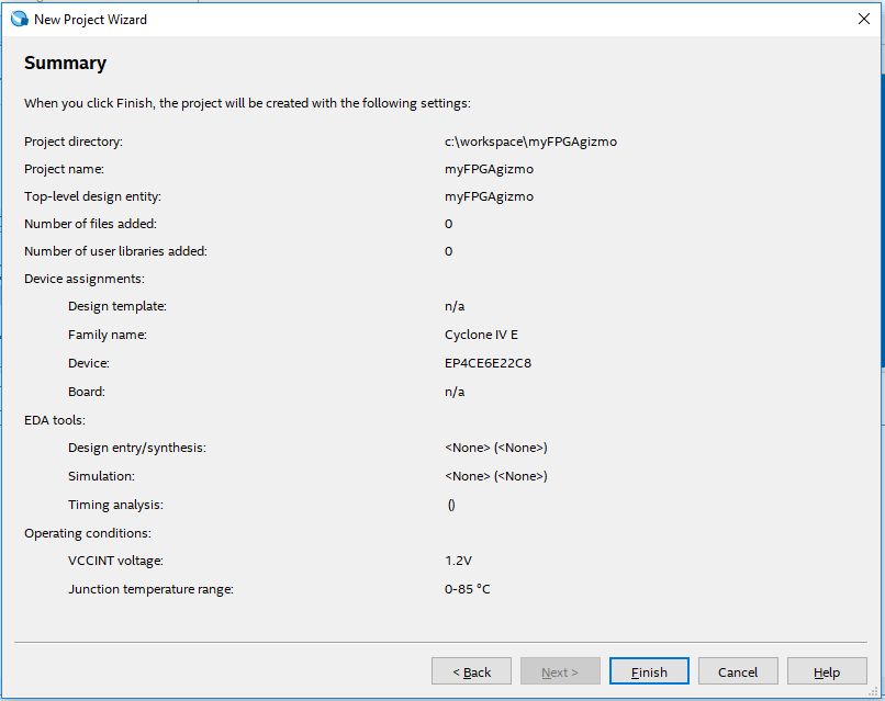
On the final Project Wizard page, the summary is shown:


Tada! All done, right? Nope. The "Wizard" still does not actually complete a project.

Double-click on "myFPGAgizmo" to edit the code, and a nice, less-than-intuitive error pops up:
Can't find design entity "myFPGAgizmo".
Not exactly to most intuitive error message for a newbie. 


Good luck finding "Add Design Entity" in the menu. Here, you just need to know that a new Design File needs to be manually added (why the wizard does not do this, I do not know).

So from what I can tell:  a source "File" == "Design Entity".

File - New - Verilog HDL File:


Quartus does not give you an opportunity to name this file when it is first created. Only at save time will it prompt to give it a new name. Visual Studio users will not be impressed.


Now another important note: The name of the module MUST MATCH the name of the "top level" file name, and it is case sensitive. The "top level design entity" is that file first listed. You just need to know this. Otherwise the Quartus software gives the less-than-intuitive error message:
Top level design entity "myFPGAgizmo" is undefined 
Here the "myFPGAgimoName" needs to be the same as the file name "myFPGAgizmo":


So after dealing with those annoyances the learning curve, I was finally able to write some Verilog that I found in another tutorial (see page 14):


module myFPGAgizmo (x1, x2, f); 
  input x1, x2; 
  output f; 
  assign f = (x1 & ~x2)|(~x1 & x2); 
endmodule 


This is where things get interesting. It is one thing to write some code, but getting it to interface to the real world is what makes it fun! Normally I/O is abstracted through complex device drivers and API calls. However, it does not get much more direct in FPGA programming, as the actual pins on the chip are assigned to variables in our code! Even better, there's no bizarre renumbering that I find ridiculously frustrating in the world of Arduino programming. There's a single pin number. Ahhh. What bliss.


As can be seen in the schematic, Pin 87 is LED4, and Pins 88 and 89 are tied to keys (button switches) KEY1 and KEY2 (but yes, instead labeled S1 and S2 on the board). Yes, those are the actual pins numbers on the Cyclone IV - pins 87, 88, and 89. No big deal, right? Well, sure - but apparently not all engineers agree. Just google "pin numbering arduino" to see how many hours have been lost to frustrating abstracted re-numbering.

Once code is entered, it is compiled using the menu: Processing - Start Compilation. When the pins are not actually assigned, there will be a compiler warning:

Critical Warning (169085): No exact pin location assignment(s) for 3 pins of 3 total pins. For the list of pins please refer to the I/O Assignment Warnings table in the fitter report.
Click on Assignments - Pin Planner. (recall above, we explicitly assigned our chip part number, otherwise this feature is not available).  If you double-click in the Location column, a drop-down list will appear:


We need to assign the pins to keys and LED as shown in the schematic:


Simply close the Pin Planner and compile again. We're ready to send the FPGA code to our device!

Note the USB Blaster connection in the very first picture on this page.

Click Tools - Programmer. If the currently selected hardware says "No Hardware", click the "Hardware Setup" button (make sure your device is plugged inn, and drivers installed)....


In this case, I selected the USB Blaster by double-clicking on it.

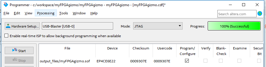
To send the FPGA code to the device, select "Processing - Start" (or simply press the "Start Button"). If successful, there will be an indication in the progress box:


That's it! There's now an XOR gate programmed in the FPGA. Press S1 or S2 to have the LED got out. Press both or leave both unpressed and the LED1 will be illuminated. Cool.

Note we've programmed the FPGA via the JTAG connector on the board. When the board is power cycled, we'll lose these changes and the board will revert back to vendor ship default.


Note that if you find cheap Cyclone boards on flea bay, the most recent version of Quartus does NOT support the older chips! I sadly learned this after buying a cheap, bare-bones Cyclone II and then noticed it was not listed as a device option in the Quartus IDE. The latest version supporting the Cyclone II is Quartus version 13.0sp1 from 2013. (I wonder if side-by-side installs are supported? I didn't try)

Here's a chart of supported devices vs Quartus versions specifically the Cyclone series:


That's it for now... send me a message on twitter if you have any feedback / suggestions / notice any typos.


Resources, Inspiration, Credits, and Other Links:


Tuesday, July 4, 2017

Converting a Blue Pill STM32F103 board to a Black Magic Probe

Recently, I learned about the really awesome Black Magic Probe - an interesting JTAG and SWD adapter that essentially has its own, built-in OpenOCD server... so you can use only the GDB client to connect directly to this device for debugging! I've been meaning to place an order for one, but then I ran across this article that converts an STM32F103 "Blue Pill" board to a Black Magic Probe!

Edit: I also tried to use the Maple Mini clone, like this one unsuccessfully; Although I was able to flash the bootloader, my computer did not recognized the device when plugged into the mini-USB connector. (apparently I'm not the only one that was unsuccessful with this).

The instructions there appear very straightforward, however as soon as I saw the some of the text, I realized the guy was using a slightly different distro of linux. So I'll add my notes on using Ubuntu. My Ubuntu is in a VMWare Workstation Virtual Machine running on Windows 10. If you have a similar setup - just don't forget to connect the device as needed from host in VM - Removable Devices. The WSL Ubuntu on Windows that I have still does not yet recognize all USB devices.

Another significant issue for me turned out to the fact that the STM32F103C8T6 is (debatable: see my comment here and noted by someone else here) only a 64K device (8K for bootloader leaving 56K for app)... and the Black Magic Probe now compiles to 57K. If it was easy, it would be no fun, eh?

To get started, ensure the tool chain is installed:


sudo apt-get update
sudo apt-get install git --assume-yes
sudo apt-get install gcc-arm-none-eabi --assume-yes
sudo apt-get install dfu-util --assume-yes

cd ~/
mkdir -p workspace
cd ~/workspace/
git clone https://github.com/jsnyder/stm32loader.git # download stm32loader
git clone --recursive https://github.com/blacksphere/blackmagic.git # download Black Magic source
#git clone --recursive https://github.com/rogerclarkmelbourne/Arduino_STM32.git # optional, has stm32flash
# optional stm32flash (64 bit version)
mkdir -p tools
cd tools
wget https://github.com/rogerclarkmelbourne/Arduino_STM32/raw/master/tools/linux64/stm32flash/stm32flash
chmod +x stm32flash
cd ~/workspace/blackmagic
make
cd src
make clean && make PROBE_HOST=stlink


when all looks good, see if you can talk to your board:

sudo apt-get install python-serial
sudo chmod 777  /dev/ttyUSB0
cd ~/workspace/blackmagic/src/
python ~/workspace/stm32loader/stm32loader.py -p /dev/ttyUSB0

it should return a result like this:
Bootloader version 22
Chip id: 0x410 (STM32 Medium-density)

Ready to flash! However - note that this is where my instructions are different.

cd ~/workspace/blackmagic/src/
python ~/workspace/stm32loader/stm32loader.py -p /dev/ttyUSB0 -e -w -v blackmagic_dfu.bin

The first time I tried, there was an error (also not the jumper setting needed for BOOT0=1:
Can't init. Ensure that BOOT0 is enabled and reset device
Traceback (most recent call last):
  File "/home/gojimmypi/workspace/stm32loader/stm32loader.py", line 436, in 
    bootversion = cmd.cmdGet()
  File "/home/gojimmypi/workspace/stm32loader/stm32loader.py", line 118, in cmdGet
    if self.cmdGeneric(0x00):
  File "/home/gojimmypi/workspace/stm32loader/stm32loader.py", line 115, in cmdGeneric
    return self._wait_for_ask(hex(cmd))
  File "/home/gojimmypi/workspace/stm32loader/stm32loader.py", line 88, in _wait_for_ask
    raise CmdException("NACK "+info)
__main__.CmdException: NACK 0x0
So just as the error hint said, I pressed the reset button and tried again. Success! Output looks like this:
Bootloader version 22
Chip id: 0x410 (STM32 Medium-density)
Write 256 bytes at 0x8000000
Write 256 bytes at 0x8000100
  [..snip..]
Write 256 bytes at 0x8001900
Write 256 bytes at 0x8001A00
Read 256 bytes at 0x8000000
Read 256 bytes at 0x8000100
  [..snip..]
Read 256 bytes at 0x8001900
Read 256 bytes at 0x8001A00
Verification OK
DFU loader done! Be sure to move jumpers back to default of "0" and press reset again. The instructions that I followed indicated that the USB device should be disconnected and reconnected. Not much interesting or different there upon re-insertion. Device is still a cp2104 on /dev/ttyUSB0
[927124.098974] usb 2-2.1: new full-speed USB device number 18 using uhci_hcd
[927124.418782] usb 2-2.1: New USB device found, idVendor=10c4, idProduct=ea60
[927124.418783] usb 2-2.1: New USB device strings: Mfr=1, Product=2, SerialNumber=3
[927124.418784] usb 2-2.1: Product: CP2104 USB to UART Bridge Controller
[927124.418785] usb 2-2.1: Manufacturer: Silicon Labs
[927124.418786] usb 2-2.1: SerialNumber: 012345678
[927124.424936] cp210x 2-2.1:1.0: cp210x converter detected
[927124.433135] usb 2-2.1: cp210x converter now attached to ttyUSB0 
The first time I ran dfu-util:
dfu-util -d 1d50:6018,:6017 -s 0x08002000:leave -D blackmagic.bin
I received an error:
dfu-util 0.8

Copyright 2005-2009 Weston Schmidt, Harald Welte and OpenMoko Inc.
Copyright 2010-2014 Tormod Volden and Stefan Schmidt
This program is Free Software and has ABSOLUTELY NO WARRANTY
Please report bugs to dfu-util@lists.gnumonks.org

dfu-util: Invalid DFU suffix signature
dfu-util: A valid DFU suffix will be required in a future dfu-util release!!!
dfu-util: No DFU capable USB device available
I had 2 new devices: /dev/serial and /dev/ttyUSB0 when plugged in.

The reason for the error? I missed the MOST IMPORTANT PART:

Disconnect everything and use the USB to connect.

The Black Magic probe uses the micro USB connector, NOT the Serial TTL! (oops) Sure enough, the device is now listed in Device Manager:


A word of caution here: if you happen to use different sources of power, beware of ground loops. I highly recommend only 1 source of power (either the USB TTY/UART or onboard Micro USB. This could be particularly important if they are on different physical computers, using a USB hub, etc.

When you remove the TTY/UART and connect the USB port on the Blue Pill, you should see something like this with dmesg:

[937218.226791] usb 2-2.1: USB disconnect, device number 22
[937218.227053] cp210x ttyUSB0: cp210x converter now disconnected from ttyUSB0
[937218.227064] cp210x 2-2.1:1.0: device disconnected
[937223.643635] usb 2-2.1: new full-speed USB device number 23 using uhci_hcd
[937223.959267] usb 2-2.1: New USB device found, idVendor=10c4, idProduct=ea60
[937223.959269] usb 2-2.1: New USB device strings: Mfr=1, Product=2, SerialNumber=3
[937223.959271] usb 2-2.1: Product: CP2104 USB to UART Bridge Controller
[937223.959272] usb 2-2.1: Manufacturer: Silicon Labs
[937223.959273] usb 2-2.1: SerialNumber: 01234567
[937223.967154] cp210x 2-2.1:1.0: cp210x converter detected
[937223.973711] usb 2-2.1: cp210x converter now attached to ttyUSB0
[937258.140246] usb 2-2.1: USB disconnect, device number 23
[937258.144289] cp210x ttyUSB0: cp210x converter now disconnected from ttyUSB0
[937258.144327] cp210x 2-2.1:1.0: device disconnected

[938012.539892] usb 2-2.1: new full-speed USB device number 24 using uhci_hcd
[938012.886453] usb 2-2.1: New USB device found, idVendor=1d50, idProduct=6017
[938012.886455] usb 2-2.1: New USB device strings: Mfr=1, Product=2, SerialNumber=3
[938012.886472] usb 2-2.1: Product: Black Magic (Upgrade) for STLink/Discovery, (Firmware v1.6.1-43-g984f8b3)
[938012.886474] usb 2-2.1: Manufacturer: Black Sphere Technologies
[938012.886474] usb 2-2.1: SerialNumber: 76543210
Unfortunately dfu-util -l is not happy:

dfu-util 0.8

Copyright 2005-2009 Weston Schmidt, Harald Welte and OpenMoko Inc.
Copyright 2010-2014 Tormod Volden and Stefan Schmidt
This program is Free Software and has ABSOLUTELY NO WARRANTY
Please report bugs to dfu-util@lists.gnumonks.org

dfu-util: Cannot open DFU device 1d50:6017
To confirm the device is there,lsusb shows the device as "OpenMoko":

Bus 001 Device 001: ID 1d6b:0002 Linux Foundation 2.0 root hub
Bus 002 Device 025: ID 1d50:6017 OpenMoko, Inc.
Bus 002 Device 003: ID 0e0f:0002 VMware, Inc. Virtual USB Hub
Bus 002 Device 002: ID 0e0f:0003 VMware, Inc. Virtual Mouse
Bus 002 Device 001: ID 1d6b:0001 Linux Foundation 1.1 root hub
You can also view just the device you are looking for with the -d parameter:
lsusb -d 1d50:
(don't forget the trailing colon ":"!

Ok, not obvious - but the problem here is one again permissions. So run the command with sudo:

sudo dfu-util -l
If successful, the output should look like this:

dfu-util 0.8

Copyright 2005-2009 Weston Schmidt, Harald Welte and OpenMoko Inc.
Copyright 2010-2014 Tormod Volden and Stefan Schmidt
This program is Free Software and has ABSOLUTELY NO WARRANTY
Please report bugs to dfu-util@lists.gnumonks.org

Found DFU: [1d50:6017] ver=0100, devnum=27, cfg=1, intf=0, alt=0, name="@Internal Flash /0x08000000/8*001Ka,056*001Kg", serial="76543210"


Once you can see the device, run dfu-util with sudo:


sudo dfu-util -d 1d50:6018,:6017 -s 0x08002000:leave -D blackmagic.bin
I received an error, that sure looks like an out of memory issue:

dfu-util 0.8

Copyright 2005-2009 Weston Schmidt, Harald Welte and OpenMoko Inc.
Copyright 2010-2014 Tormod Volden and Stefan Schmidt
This program is Free Software and has ABSOLUTELY NO WARRANTY
Please report bugs to dfu-util@lists.gnumonks.org

dfu-util: Invalid DFU suffix signature
dfu-util: A valid DFU suffix will be required in a future dfu-util release!!!
Opening DFU capable USB device...
ID 1d50:6017
Run-time device DFU version 011a
Claiming USB DFU Interface...
Setting Alternate Setting #0 ...
Determining device status: state = dfuIDLE, status = 0
dfuIDLE, continuing
DFU mode device DFU version 011a
Device returned transfer size 1024
DfuSe interface name: "Internal Flash   "
Downloading to address = 0x08002000, size = 58364
dfu-util: Last page at 0x080103fb is not writeable
So I found other instructions relating to STM Discovery as a Black Magic Probe that indicated dfu_upgrade.bin needed to be loaded (I was willing to try anything!)

sudo dfu-util -d 1d50:6018,:6017 -s 0x08002000:leave -D dfu_upgrade.bin
The results are a bit more promising:

dfu-util 0.8

Copyright 2005-2009 Weston Schmidt, Harald Welte and OpenMoko Inc.
Copyright 2010-2014 Tormod Volden and Stefan Schmidt
This program is Free Software and has ABSOLUTELY NO WARRANTY
Please report bugs to dfu-util@lists.gnumonks.org

dfu-util: Invalid DFU suffix signature
dfu-util: A valid DFU suffix will be required in a future dfu-util release!!!
Opening DFU capable USB device...
ID 1d50:6017
Run-time device DFU version 011a
Claiming USB DFU Interface...
Setting Alternate Setting #0 ...
Determining device status: state = dfuIDLE, status = 0
dfuIDLE, continuing
DFU mode device DFU version 011a
Device returned transfer size 1024
DfuSe interface name: "Internal Flash   "
Downloading to address = 0x08002000, size = 6764
Download        [=========================] 100%         6764 bytes
Download done.
File downloaded successfully
Transitioning to dfuMANIFEST state
But even with that - I was completely unable to use dfu-util to program the Blue Pill with a 57K blackmagic.bin file. Even after power cycle, reset, etc. So I put the board back into USART programming mode (BOOT0 jumper=1, BOOT1 jumper=0) and used the ST Flash Loader app on Windows. The device is initially detected as a 65K device:


However on the next screen, apparently you can force it into 128K mode:


The select the blackmagic.bin file, click the "Erase necessary pages", select an address of 0x8002000 and check the "Verify after download" checkbox:


If successful, you should see:

I should point out that several times I received a verify error at this last verify step (I was really convinced I had a 64K-only device). After trying again the next day - things started working immediately and I never again saw the verify error, even after doing a full erase and starting over. YMMV.

Keep in mind that the fact that we are using 128K on a 64K device is rather dangerous. In all likelihood, the manufacturer does an exhaustive memory test: throws away the ones with an error in the first 64K, market the ones with an error in the second 64K as only a 64K STM32f103C8T6 device, and label the ones with no error as 128K STM32f103CBT6 devices. Although this may be a fun Saturday afternoon project, if you are serious about actually using and depending on a BlackMagic probe for real debugging, consider buying one. (besides, always good to support the developer).  When you are elbows-deep in debugging your own project, you really don't want a questionable debugger.

So at this point, I'm not even sure the dfu bootloader is needed, if we are loading the blackmagic.bin file this way.

My particular debugging experiment uses the STM Smart V2 board as a target, and using my STM32 to ST7735 TFT LCD display example with the source on github. This is somewhat of a convoluted setup, as the project is in Visual Studio 2017 (on Windows 10) with the VisualGDB Extension from Sysprogs.

As previously mentioned, I'm running my Ubuntu in a VM, and I have samba installed so that on Windows I can map a drive  (C$ is root  /):

net use z: \\192.168.1.30\c$ /user:gojimmypi

Debugging connections from Blue Pill board configured as a Black Magic Probe (micro usb connected to Ubuntu):

Connecting the Blue Pill Black Magic Probe to an STM Smart V2 board:


cd  ~/workspace
git clone https://github.com/gojimmypi/STM32-ST7735.git

then open the solution Z:\home\gojimmypi\workspace\STM32-ST7735\STM32-ST7735.sln in Visual Studio and compile.


cd  ~/workspace/STM32-ST7735/STM32-ST7735
arm-none-eabi-gdb -d ./ -f ~/workspace/STM32-ST7735/VisualGDB/Debug/STM32-ST7735 -tui
ls /dev/ttyACM* -al

then in GDB, connect with the first ttyACM[n] device (the second one is a serial port). Mine were originally ttyACM0 and ttyACM1, but then later changed to ttyACM1 and ttyACM2 (no idea how/why). I even saw an instance while debugging that ttyACM1 changed to ttyACM0 yes leaving me with (ttyACM0 and ttyACM2).Weird.
Anyhow, here are some useful GDB commands to get started:

target extended-remote /dev/ttyACM1
monitor swdp_scan
attach 1


If successful you should see something like this:

GNU gdb (7.10-1ubuntu3+9) 7.10
Copyright (C) 2015 Free Software Foundation, Inc.
License GPLv3+: GNU GPL version 3 or later 
This is free software: you are free to change and redistribute it.
There is NO WARRANTY, to the extent permitted by law.  Type "show copying"
and "show warranty" for details.
This GDB was configured as "--host=x86_64-linux-gnu --target=arm-none-eabi".
Type "show configuration" for configuration details.
For bug reporting instructions, please see:
.
Find the GDB manual and other documentation resources online at:
.
For help, type "help".
Type "apropos word" to search for commands related to "word"...
Reading symbols from /home/gojimmypi/workspace/STM32-ST7735/VisualGDB/Debug/STM32-ST7735...done.
(gdb) target extended-remote /dev/ttyACM1
Remote debugging using /dev/ttyACM1
(gdb) monitor swdp_scan
Target voltage: unknown
Available Targets:
No. Att Driver
 1      STM32F1 medium density
(gdb) attach 1
Attaching to program: /home/gojimmypi/workspace/STM32-ST7735/VisualGDB/Debug/STM32-ST7735, Remote target
0x08001514 in SetSysClockTo72 () at system_stm32f10x.c:993
(gdb)

sample


Resources, Inspiration, Credits, and Other Links:


Find gojimmypi at gojimmypi.github.io

I'm currently working on my new blog home at  gojimmypi.github.io After implementing a variety of features such as dark mode , syntax hi...