Tuesday, December 24, 2019

ULX3S and IceStudio

Today I learned that IceStudio supports the ULX3S! I thought I'd first try it in WSL Ubuntu.

I'm not sure if X-Windows server is needed, but I have some notes in a prior blog post to use cygwin from WSL.

sudo apt-get update  
sudo apt-get upgrade 
sudo apt-get install nodejs
sudo apt-get install npm
node -v
cd ~/workspace/

## see https://github.com/FPGAwars/icestudio#download
##
git clone https://github.com/FPGAwars/icestudio.git
cd icestudio

## Do we need to have an X-Windows server running?
##
export DISPLAY=:0 # you may wish you put in this your ~/.bashrc
cp /mnt/c/cygwin64/home/gojimmypi/.Xauthority   ~/.Xauthority

## test X-Windows
xclock

## ensure we are on the develop branch
##
git status 

npm install
npm start

Unforunately, this left me in a state of "waiting..."


gojimmypi:~/workspace/icestudio
$ npm start

> icestudio@0.5.1 start /home/gojimmypi/workspace/icestudio
> grunt serve

Running "nggettext_compile:all" (nggettext_compile) task

Running "watch:scripts" (watch) task
Waiting...
Running "wiredep:task" (wiredep) task

Running "exec:stopNW" (exec) task

Running "exec:nw" (exec) task

Done.
Completed in 3.118s at Tue Dec 24 2019 06:57:33 GMT-0800 (PST) - Waiting...


For Windows, download the NodeJS and NPM. I did get it working, but see this icestudio GitHub issue #368. More to come...

Resources and links:

Monday, December 9, 2019

REST API SOAP Payload Sniffing

Visual Studio has a tremendously helpful code generator for accessing a SOAP API without needing to worry about the transport and decoding issues. Simply right click on the project and select Add, "Connected Service".


This should bring up a tabbed window to add Connected Services. We're interested in the WCF:


Enter the URI for the SOAP interface of interest and press the Go button. If all went well, the available service(s) should be listed. Enter a namespace and click next to see additional options. For more information see the documentation: Use the WCF Web Service Reference Provider Tool.

For more details on WCF, see the github dotnet wcf repo.

This abstraction of course has a flip side: The actual data transferred is buried deep in the internals so any single-step debugging cannot "see" the raw HTML/raw XML payload. This is where Fiddler comes in to help. (yes, if you've not used Fiddler for some time, it was bought by Telerik, which was bought by Progress).

Before getting started, the netsh command will be used. It is probably a good idea to see how it is currently configured before making changes. To see the current setting, use: netsh winhttp dump

The default typically looks like this:


# -----------------------------------------
# WinHTTP Proxy Configuration
# -----------------------------------------
pushd winhttp

reset proxy

popd

# End of WinHTTP Proxy Configuration


To allow Fiddler to see the packets it needs to run in "Administrative" mode in Windows. Either right-click on the icon and select "Run as Administrator" or after searching for the app, select from the start menu:


We'll need to set a proxy to ensure all http transfers pass through Fiddler. Otherwise it just sits there idle. So yes, the command prompt needs to be running as administrator here, too. This is the command to setup the proxy:

netsh winhttp set proxy 127.0.0.1:8888

When done, return to default:

netsh winhttp reset proxy


If you don't return things to default, web browsers, Outlook, and potentially other things will misbehave, particularly when existing Fiddler. A reboot also restores the proper netsh default state.

A few notes on Fiddler:

  • The `Decode` feature only decodes moving forward. If you see gzip-encoded payload, pressing the button will not decode existing captures.
  • Only newly seen request/responses will be decoded. Press F12 or File - Capture Traffic to being sniffing. A checkbox means packet sniffing is active.
  • Data is viewed under the Inspectors tab. I personally prefer the XML view. 

This was all related to the WCF GitHub Issue 4071 that I opened up for some problems I encountered when serializing a SOAP response in a dotnet core command line app.

Monday, October 28, 2019

NanoVNA Notes

Some notes on the NanoVNA -  The tiny, inexpensive Vector Network Analyzer.

A few months ago, I purchased the amazing NanoVNA on ebay for about 50 bucks. What an impressive work of engineering for such a ridiculously low price! Ok, admittedly the really cool stuff comes from the people that are working on open source software. That hardware would have much less value without the software,

When ordering a new VNA, pay attention to what you get and what you might need. Mine came with the essential 50 ohm load, open, and short SMA plugs, 2 SMA cables, a USB-C cable, and a tin box.

I didn't know it at the time (although probably not a surprise)... but there are a lot of imitations. ymmv. The only "official" one that I have since become aware of, is this Nooelec kit. Considering the time and hassle of ordering connectors that otherwise come included with this kit - I probably would have purchased it instead, had I known about it.

Here's mine in a EMI-protective tin (that normally should have the lid on when you are using it!) measuring a cheap LoRa antenna:


The tin box is much more than a carrying case! I drilled some holes in mine and used it as a protective shield. Measuring antenna characteristics with, say your computer just inches away will almost certainly cause interference and erroneous results.

I ended up paying nearly the same amount for a variety of adapters and connectors. There's an amazing variety available. SMA Male to IPX ufl (e.g. the antenna adapter shown above), SMA to BNC (e.g. Oscilloscope probe), SMA to F-Type (e.g. cable TV), F-type coax male / F-type coax female and a variety of others are things to consider - depending on the need.

It's probably a personality disorder quality attribute, but here are the adapters I ordered after I had my NanoVNA but realized I didn't have the right one on hand:


The little blue 3D-printed nut spinners were a cool gift. I had never used them, but certainly recommend them now! They are quite handy for tightening the SMA connectors,

A couple of key places for the NanoVNA user to be aware of:

Once you have a NanoVNA, unless you want to upgrade firmware - probably the only thing of interest (other than the documentation) - is the NanoVNA Saver software.

Calibration is important! 

There's an excellent, easy-to-understand sequence of pictures that illustrates the plugs, cables, and connections for each step of calibration. From the cho45 NanoVNA manual:

Calibration should basically be performed whenever the frequency range to be measured is changed. If the error is corrected correctly, the calibration status display on the screen will Cn D R S T Xbe. n is the data number being loaded.
However, NanoVNA can complement the existing calibration information and display to some extent correct. This will happen if the frequency range is changed after loading the calibration data. At this time, the calibration status is displayed on the screen cn D R S T Xn is the data number being loaded.
  1. Reset current calibration state CAL RESET
  2. Connect the OPEN standard to the CH0 port CAL CALIBRATE OPENand execute.
  3. Connect the SHORT standard to the CH0 port CAL CALIBRATE SHORTand execute.
  4. Connect the LOAD standard to the CH0 port CAL CALIBRATE LOADand execute.
  5. Connect the LOAD standard to the CH0 and CH1 ports CAL CALIBRATE ISOLNand execute. If there is only one load, the CH0 port can be left unconnected.
  6. Connect the cables to the CH0 and CH1 ports, connect the cables with the through connectors, CAL CALIBRATE THRUand execute.
  7. Finish calibration and calculate error correction information CAL CALIBRATE DONE
  8. Specify the data number and save.CAL CALIBRATE SAVE SAVE 0
* Each calibration data must be imported after the display is sufficiently stable.

Firmware notes:

One of the most important things that I learned during the upgrade process is that there are apparently TWO different types of firmware. The standard version and the "AA" (Antenna Analyzer) version. Upload the wrong firmware, and I saw this mess of squiggly lines on the screen:

Not the NanoVNA you want to see,
This was the result of my compiled version off of GitHub. I was never able to get it to work. :/

Fortunately, one of the folks on the user groups posted some useful files that helped me recover.

When upgrading the firmware, DON'T FORGET THE JUMPER on the board. Yes, this is in upper case as even though it was listed in the instructions, I forgot that part and used Zadig the change the USB drivers BEFORE the jumper was in place. Don't do that.

In fact, I didn't need Zadig at all, erm, once the BOOT0 jumper was in place. For more info on the dfu-util and Zadig, see Scott Hanselman's Blog on How to fix dfu-util, STM, WinUSB, Zadig, Bootloaders and other Firmware Flashing issues on Windows.

The board should be powered on with the BOOT0 jumper in place. You can remove the jumper after turning on the power and before uploading the firmware. I've left the jumper in place, uploaded the firmware, then powered down and removed the jumper. It seemed to work just fine.

My BOOT0 jumper was in a completely different location (on a completely different board) as compared to the one on the ttrftech docs. Note my jumper was located under the batter LiPo connector:

My NanoVNA with a temporary jumper at BOOT0


Note that more recent versions of the firmware have the ability to put the board into DFU mode. See the config menu option.

Windows (and WSL Linux users) can download the dfu-util from SourceForce (too bad that site is such a haven for excessive ads). I used the 64 bit Version 0.9.

Despite there being an apt-get version of dfu-util for WSL Ubuntu, I was not able to get that version to recognize the NanoVNA. Fortunately Windows apps can also be used in WSL. Don't forget the "./" for WSL.

./dfu-util.exe -d 0483:df11 -a 0 -s 0x08000000:leave -D build/ch.bin


More to come...

Saturday, June 1, 2019

ULX3S and Visual Micro in Visual Studio 2019

This blog is a walk-though using the Visual Micro Arduino IDE in Visual Studio 2019 to program the ESP32 on the Radiona ULX3S. For more information on the ULX3S see my Day 1 intro, Using ujprog on WSL or MinGW, and Notes on ulx3s FPGA: Yosys, Verilog, VHDL, vhdl2vl (Convert VHDL to Verilog). Here's the ULX3S with the SPIDriver.

ULX3S with SPIDriver board
There are some brief online instructions for manually installing Visual Micro, or you can follow along here, using the VisualMicro example for the ULX3Son GitHub:

In Visual Studio 2019, click on Extensions - Manage Extensions.


Select "online" in the left pane and type "Arduino" in the search box:


Note the 5 stars reviews from hundreds of users. Yes, it is a very cool extension. :)

Next, click on the "Download" button. You'll need to restart Visual Studio 2019.

Be sure to wait for the VSIX installer screen! The first time I did this, I simply launched Visual Studio right away, and the Visual Micro Extension was no where to be found! Before launching Visual Studio, you should see this screen:


Then after a warning about system changes, this prompt:


Click the "Modify" button to continue. Upon completion, there should be a message "Modifications Complete"


When Visual Studio is next launched, click on "Create a new project"


There are many project types, so type "Arduino" in the search box:


Select "Arduino Project" and click the Next button.


Give the project a name, and a location to store it. In this case, I am saving it in my ULX3S examples fork directory, to create a pull request to the official ULX3S Examples.

After clicking  the "Create" button, a familiar Arduino-style code template is created, with the setup() and loop() functions:


So that's the easy part. Now things get more interesting. The ESP32 on the ULX3S sits behind the FPGA chip. This means the only way to program the ESP32, is to have code on the ULX3S that performs a "pass through" function of external physical pins to the ESP32 pins through the FPGA.

schematic showing the ESP32 to FPGA connections


Fortunately, the ULX3S typically ships with the pass-though FPGA app already loaded. If not, the FPGA source code can be found here. Note there are three different versions: the Diamond VHDL that emard wrote, a Diamond Verilog that I converted from emard's VHDL, and finally an Open Source Verilog version that uses yosys and nextpnr. (hm, it looks like from the most recent comments I need to get the open source version working properly - I'll need to look into that)

If you are not ready to jump into the synthesis of FPGA bit files yet, you can use the passthru image file passthru_ulx3s_v20_12k.bit and load it onto the ESP32 using the ujprog tool. If you don't feel like building your own, there's a copy of both the bin directory.


if NOT EXIST c:\workspace mkdir c:\workspace
git clone https://github.com/gojimmypi/ulx3s-examples.git c:\workspace\ulx3s-examples
c:
cd \workspace\ulx3s-examples\VisualMicro\bin\
.\ujprog.exe passthru.bit


If "Cannot find JTAG cable" is encountered, remember that WSL is still not supporting native USB drivers. If you are using the Windows executable version and you see that message try changing the ULX3S drivers back to FTDI particularly if you don't see your ULX3S in the Ports (COM & LPT) container in device manager. WSL can be finicky, and even have different results whether executing from a Linux directory or DOS (e.g. /mnt/c/). And yes, native Windows executable files can be launched from WSL! cool.

Visual Studio seemed to have defaulted to all the correct values for me (I'm note sure if perhaps it remembered values from Visual Studio 2017) Here they are for reference:


Of particular interest is ensuring the proper COM port is selected, near the bottom of the settings list. I didn't see the actual ESP32 device listed (WROOM-32), so I used the ESP32 Dev Module setting.

Once the pass through FPGA binary has been successfully uploaded, the simplest way to compile and upload the Arduino code via Visual Micro is to press F5 or the big green "start" button! That's it!

Note that one of the amazing things about the Visual Micro IDE, is they have implemented a debugger that does not require a hardware JTAG device! Here's my ULX3S ESP32 paused at a breakpoint:


Now onto that SPI Driver! Stay tuned for more....


Saturday, May 18, 2019

FPGA Boards and Programming the Numato Mimas V2

I've been learning about FPGA devices... recording my thoughts, experiences, and technical notes here on this blog. In the span of just a few weeks - two different devices caught my attention. One is the Numato Mimas V2 Spartan 6 FPGA Development Board with DDR SDRAM complete with audio, video, SD slot, 7-segment display, on-board LEDs, and more... for about 50 bucks.

Numato Mimas-V2 FPGA Development Board with demo code running

The other is the old, now obsolete but excellent new learning opportunity Pano Logic zero client that happen to also have a Xilinx(TM) chip on board:


In particular, Tom Verbeure has these impressive Pano Logic Zero Logic G1 and G2 GitHub repositories (see also this Hackaday project).

Last year, I bought one of those Altera Cylone IV boards on ebay, and wrote a little blog about it. Setup was a long and tedious process. I never ended up doing much with that board.

More recently - I've been tinkering with the Lattice iCE40 chips, such as the one found in the awesome tinyFPGA BX board and the somewhat rare but much more feature-rich ULX3S board (which is also in the running to hopefully take first place in the Hackaday Contest, vote for it here). I'm also awaiting my first iCEBreaker board from 1bitsquared that certainly looks interesting.

I have several blog posts on the iCE40 FPGA, including using the tinyFPGA on WSL, loading up a soft RISC-V on the tinyFPGA, and more recently some ULX3S topics: first day more on using WSL, some samples and walk-through examples and most recently my AD/DA with the ULX3S.

In addition to proprietary vendor tools - I've been using yosys & nextpnr open source FPGA programming tools. The community is really awesome, with people impressively helpful and patient despite my sometimes clearly newbie questions. Although I have a background in Electronic Engineering, I work at the Day Job as a Senior Software Engineer (mainly C#, SQL). Learning FPGA is something I've wanted to do for quite some time. This has been quite a humbling and interesting experience.

Certainly one of the interesting topics related to FPGA programming is Formal Verification. I've been reading a lot about this, but many of the examples have been with quite complex systems. Fortunately @zipcpu published An Exercise in using Formal Induction: a small and focused walk-though that illustrates the concepts of Formal Verification with a relatively simple FPGA shift register.

I've had some reservations about the Xilinx chips - not the least concern of which was the story earlier this year where Xilinx sent lawyers after online educators. Additionally, their Vivado software costs thousands of dollars, making the kitchen-table learning experience quite a bit less desirable. Still, one cannot deny they are a major player in the FPGA world. Despite the sharp drop on April 24/25 - their stock appears to still be doing well over the course of the last year. Further, the SPARTAN-6 chips do not require Vivado (glad I learned that before downloading the full 18+ gig app! )
"Spartan-6 needs ISE, not Vivado - Vivado is only for 7-series and newer"
    -- @fpga_dave
I'm downloading the ISE which is considerably smaller, but still gigs in size. Any discussion on the ISE should certainly include this blog on Installing Xilinx ISE inside a Docker Container.  I think I'll try a normal install before venturing into Docker territory.

Further, the Xilinx chips do not seem to be supported by the open source yosys & nextpnr the way the iCE40 chips are. So it appears we are  locked in to proprietary vendor tools for the Spartan-6 FPGA development.

The MimasV2 board has a Xilinx SPARTAN XC6SLX9 CSG324 FPGA, which appears to be the second-to-lowest-end device with 9,152 logic cells and 106 user IOs. Still, this is probably more than adequate for a learning / development board.

Excerpt from Xilinx(TM) Spartan-6 Family Overview PDF  

My first experience with latest ISE was really horrible. The "Windows version" is actually an Oracle VirtuaBox linux VM. The Xilinx software might be ok, but the VM in which is runs is not cool. Perhaps I am just used to the clean and effective VM machines provided by the folks at VMWare. But in my case, the mouse controls were simply horrible & lagged.  The keyboard control is wonky: hold down the right-ctrl key. I am right handed, my right hand is usually on the mouse; super annoying to switch between the VM and my host. The list goes on.  (Update: after a Windows reboot, the laggy mouse in the VirtualBox seems to have been resolved. Other operations are still wonky)

In short, I highly recommend an older version of the ISE to run natively on Windows. The official version that was supported was Windows 7. So ymmv in Windows 10. I'm using the 13.1 version (Update - There's a non-VM version 14.7 of the ISE) that can be downloaded from the Xilinx archive. Yes, you'll need an account to login and the free license will still be node-locked to your MAC address. Some of the ebay vendors include a disk with software.

UPDATE: It appears that the VirtualBox version was probably created because of an apparent problem with JTAG drivers in Windows 10, given an "The Platform Cable USB is not detected" error like this:

Enumerating cables. Please wait.
PROGRESS_START - Starting Operation.
Connecting to cable (Usb Port - USB21).
Checking cable driver.
 Source driver files not found.
The Platform Cable USB is not detected. Please connect a cable.If a cable is connected, please disconnect
and reconnect to the usb port, follow the instructions in the 'Found New Hardware Wizard', then retry
the Cable Setup operation.
PROGRESS_END - End Operation.
Elapsed time =      1 sec.

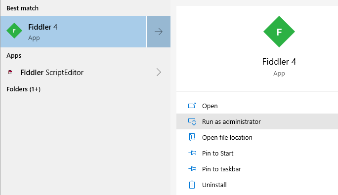
I found that running iMPACT as Administrator in Windows solved this problem for me:

Run iMPACT as Administrator to resolve USB  JTAG device problems.


There are a bunch of apps that get installed with the Xilinx software. The development environment of interest is the ISE, listed under either 32bit or 64bit "Project Navigator". Although I have a 64 bit machine, the 32 bit software seemed to be more reliable.


If you try to open a Xilinx project file such as the Numato demo, and the ISE just blinks and exits, it may be because the project file was created with a newer version. I found that simply editing the project file with your favorite text editor seems to work. Edit the version here:

xise version setting
If the ISE still exits immediately when double-clicking on an xise file, then the 64-bit version is probably launching. When I launch the 32 bit version, then manually open the xise project file, all seemed to go much more smoothly. I'm not sure why the 64 bit version is unhappy on my 64 bit Windows 10.

Numato has a bunch of sample code on GitHub, including the demo source code and an interesting HDMI driver. Here, I'm looking at the project demo in:

./FPGA/MimasV2/mimasV2Demo/mimasV2Demo.xise

The Numato sample code README indicates that to create a binary file in the ISE:
Right click on the "Generate Programming Files" process in the process window and select "Rerun all".
That's great - if you can find the "Generate Programming Files":

By default, the "Generate Programming Files" is not visible.

In order to actually create the binary file, click on the MimasV2TopModuleLX9 filename in the Hierarchy window, then the Generate Programming Files will appear in the lower pane:


Unlike Visual Studio, that indicates at compile time where the binary files are... there was no indication in the ISE where the bit and bin files ended up. They ended up in the same directory as the xise file. Perhaps not exactly the best organization of files, but at least easy to find:

MimasV2 sample code bin and bit files.
The bin and bit files are different sizes. I used the bin file.

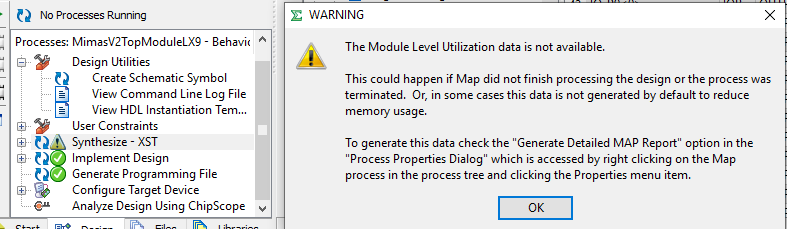
Poking around at things, I saw this message when clicking on "Module Level Utilization":


I read that about 5 times while trying to find where, exactly it was referring to. I'm glad I saved the snip of that, as after closing it, future clicks on the "Module Level Utilization" no longer gave the information.

The actual location is found under "Implement Design". Right-click on "Map" and select "Process Properties":


Then check this box:


Re-run the Map (right click, re-run)... and indeed the Module Level Utilization is now available:


One thing in particular to the ISE newbie, is how to actually get binary data onto the FPGA. Tools - Program? No, of course not. There's something called "iMPACT" that is used for that. :/  Clearly someone needs to hire a better UI/UX expert.

Before attempting to program the Numato board, ensure Windows has the proper USB drivers installed. Although Windows will try to auto-install drivers for the Numato board, custom drivers are needed. This too can be downloaded from the Numato site here. Curiously, the Numato drivers are only two small files: a cat and inf.

Note that several times after bringing my computer out of sleep mode, Windows 10 would "forget" the drivers for the Numato board and give a warning on how a USB device is configured properly. Simply unplugging and re-plugging the USB cable seems to resolve this. Device manager should show something like this:


The folks at Numato have put together a quite nice Mimas-2 Getting Started Walk-Through that is really quite helpful. The article is clean, clear and well written.

The Numato Walk-Thru has a section on Configuring MIMAS V2 Using Configuration Tool. This tool is vastly easier and more intuitive to get up and running with code on their FPGA board. Clearly they realized that the ISE iMPACT was a bit wonky, and created their own, easy-to-upload applet. They should have included a link to that in the walk-through. Still, it was easy to find by clicking on the "downloads" link on the MimasV2 Product Page. This makes flashing firmware onto the Numato FPGA board a breeze:

Numato Mimas V2 Config tool uploading binary code to FPGA flash.
My only suggestion might be to make it open source, and/or provide a command-line version. It also might have been nice to limit the com port selection to those actually found on the computer. The most important thing is that it works: simple to use and seems to work well.

If for some reason the sample code does not run properly. Numato provides a sample bin file on the download page.

I did purchase a JTAG FPGA Programmer from ebay, like this one. Some vendors sell a CD with the software. This is certainly handy if you don't want to download gigs of software. You'll still need to get a license file from the Xilinx web site. Note that the Numato board can be programmed with a JTAG device, but does not require one.

In looking at the Pano devices, such as the G2 from Tom Verbeure, the first thing to do is get rid of the dash in  the filename. Otherwise the ISE will complain about "The directory path is not valid and cannot be used"


Navigate to the blink\ise directory and open the ise.xise file:


Disclosure: I am not affiliated with any of the entities mentioned in this blog. All opinions are my own and do not reflect that of my employer. The kind folks at Numato sent me a free Mimas-2 board stating: "in exchange of a small publication of your thoughts about it on your website".  I was not compensated in any other way.


Xilinx(TM) are is a registered trademark of Xilinx. Content in this blog is purely my personal experience and is in no way related to Xilinx the company, or any other organization. I am not endorsing or recommending for or against any product. For more Xilinx legal information see this link.


Resources, Inspiration, Credits, and Other Links:


Sunday, March 31, 2019

ULX3S FPGA Examples

March has been FPGA learning month. I created some examples that were accepted by emard into the  new ULX3S Examples repo.

ULX3S SDR with ALINX AD/DA

Last year, I wrote about the ALINX AD/DA Module that I found on fleabay. Anyone interested in this board should certainly watch the video posted by opentechlab.

Key tidbits of information from the video:

  • DAC is powered by onboard 3.3V regulator.


  • Output from the DAC is differential 3vpp; (true output is difference) each output goes though a low pass filter for anti-aliasing. 


  • Fed into AD 8056 op-amp to convert differential signal to single-ended and level shift from 3vpp to 10vpp (-5 to +5V)


  • Potentiometer is used to control gain of output.


  • There's a bit of input protection on the ADC.


  • Input filter converts 10vpp to 3vpp for ADC chip.


  • MC34063 Step-Up/Down/Inverting Switching Regulators to generate negative rail for output from single +5VDC supply.


Links:

Sunday, February 17, 2019

Notes on ulx3s FPGA: Yosys, Verilog, VHDL, vhdl2vl (Convert VHDL to Verilog)

I want to better understand my new ULX3S, and I was hoping to use FOSS FPGA tools. Here I document some things I've recently learned:

Some key points (from https://gitter.im/ulx3s/Lobby/ ):
  • the standard JTAG programming stuff only programs FPGA SRAM; So rebooting the board will "recover" it 
  • In general you have to go through a fairly tedious process involving Diamond Deployment Tool to create a SVF file to program flash, and this will be very slow Otherwise, you are just programming SRAM (update: this is no longer the case; see ujprog -j flash file.bit
-- @daveshah1
and:
  • I guess the ulx3s-passthru bitstream is by default shipped to you, when you have OLED and ESP32 in box then it makes sense to load the board with passthru.
  • Other boards without OLED and/or ESP32 are probably shipped with f32c with FAT filesystem on config flash to run self-test application at power up.
  • You can erase config flash and ESP32 with whatever you want and flash back to "factory default" from my ulx3s-bin repository.
  • passthru is old source and it needs updated makefile like in prjtrellis-dvi. Yes it tries to find diamond.
  • Passthru is very simple and it could be ported done using opensource tools only. I'm using vhd2vl. For most simple vhdl examples it works great.
  • It can't convert if VHDL source is complex/advanced and has functions and packages.
-- @emard
I case you are wondering about that second USB port (the left one, when facing them):
don't touch the second USB port - it's wired directly into FPGA and thus won't even enumerate on the PC as a serial port unless you do some serious coding at FPGA side (see TinyFPGA Bootloader project - it's pretty much all about it) ... instead, use USB1 which is wired through FT231 chip (see info here)
-- @reostat 
My favorite claims / features:
  • ULX3S is unbrickable
-- @emard
and:
  • There is no realistic chance of irreparable damage to the ULX3S in any case
-- @daveshah1

The term "iCEStorm Toolchain" does not mean Yosys, arache-pnr, nextpnr, Trellis; just iCEStorm.

Yosys, arache-pnr, nextpnr, Trellis supports only Verilog, not VHDL

I have a ULX3S 12K. The Blinky from DoctorWkt expects a 45F chip. Even when editing the original Makefile to instead use the --12 option, nextpnr-ecp5 failed:
Yosys 0.8+148 (git sha1 e112d2fb, clang 6.0.0-1ubuntu2 -fPIC -Os)
Time spent: 54% 11x read_verilog (0 sec), 9% 6x techmap (0 sec), ...
nextpnr-ecp5 --12k --json blinky.json --basecfg ulx3s_empty.config \
--lpf ulx3s_v20.lpf \
--textcfg ulx3s_out.config
unrecognised option '--12k'
Makefile:74: recipe for target 'ulx3s_out.config' failed
make: * [ulx3s_out.config] Error 255
In fact, things were looking pretty bleak, as the nextpnr-ecp5 does not even list the 12F:
nextpnr-ecp5 -- Next Generation Place and Route (git sha1 4c73061)

General options:
  -h [ --help ]             show help
  -v [ --verbose ]          verbose output
  -q [ --quiet ]            quiet mode, only errors and warnings displayed
  -l [ --log ] arg          log file, all log messages are written to this file
                            regardless of -q
  --debug                   debug output
  -f [ --force ]            keep running after errors
  --gui                     start gui
  --run arg                 python file to execute instead of default flow
  --pre-pack arg            python file to run before packing
  --pre-place arg           python file to run before placement
  --pre-route arg           python file to run before routing
  --post-route arg          python file to run after routing
  --json arg                JSON design file to ingest
  --seed arg                seed value for random number generator
  -r [ --randomize-seed ]   randomize seed value for random number generator
  --slack_redist_iter arg   number of iterations between slack redistribution
  --cstrweight arg          placer weighting for relative constraint
                            satisfaction
  --pack-only               pack design only without placement or routing
  --ignore-loops            ignore combinational loops in timing analysis
  -V [ --version ]          show version
  --test                    check architecture database integrity
  --freq arg                set target frequency for design in MHz
  --no-tmdriv               disable timing-driven placement
  --save arg                project file to write
  --load arg                project file to read

Architecture specific options:
  --25k                     set device type to LFE5U-25F
  --45k                     set device type to LFE5U-45F
  --85k                     set device type to LFE5U-85F
  --um-25k                  set device type to LFE5UM-25F
  --um-45k                  set device type to LFE5UM-45F
  --um-85k                  set device type to LFE5UM-85F
  --um5g-25k                set device type to LFE5UM5G-25F
  --um5g-45k                set device type to LFE5UM5G-45F
  --um5g-85k                set device type to LFE5UM5G-85F
  --package arg             select device package (defaults to CABGA381)
  --speed arg               select device speedgrade (6, 7 or 8)
  --basecfg arg             base chip configuration in Trellis text format
                            (deprecated)
  --override-basecfg arg    base chip configuration in Trellis text format
  --textcfg arg             textual configuration in Trellis format to write
  --lpf arg                 LPF pin constraint file(s)
@daveshah1 to the rescue once again!
pass --25k to nextpnr, remove the basecfg if your nextpnr is yesterday or today's build otherwise point it to a 25k basecfg, and then pass --idcode 0x21111043 to ecppack
-- @daveshah1

I'm not sure I would have ever guessed the 25F, and certainly not the --idcode 0x21111043 part. I pulled the latest SymbiFlow/prjtrellis and nextpnr now (git sha1 4c73061), cleaned and rebuilt everything with my new Makefile, and success to build!
[... snip ..]
Info: [ 79471,  79958) |
Info: [ 79958,  80445) |***
Info: [ 80445,  80932) |*
Info: [ 80932,  81419) |***
Info: [ 81419,  81906) |********
337 warnings, 0 errors
ecppack ulx3s_out.config ulx3s.bit --idcode 0x21111043
Now recall I am doing this all in WSL Ubuntu, so there are no native USB devices - thus I am forced to use the Windows version of ujprog to actually upload the code to the ULX3S board.

The amazing thing here - is that Windows applications can be run from within WSL!

This seems to completely circumvent the "No Native USB Devices" in WSL. For example, here's the same app compiled for linux, not finding the JTAG device:


I'm using the very latest FTDI code in my fork of the f32c tools (I created this PR #9). I still encountered some problems with the syntax of the ujprog. I opened issue #10, which was promptly closed - regarding the expected operation. Bottom line is this is the syntax that works:
C:\workspace-git\f32c_tools\ujprog>ujprog ulx3s.bit
ULX2S / ULX3S JTAG programmer v 3.0.92 (built Feb 13 2019 12:27:20)
Using USB cable: ULX3S FPGA 12K v3.0.3
Programming: 100%
Completed in 18.66 seconds.
And I learned a few more things in the close comment:
JTAG doesn't work in COM mode, so no wonder that uploading a bitstream can't work that way, especially not when using the -a modifier, which tells the ujprog to send the file as a stream of bytes.
-- gornjas
From gitter:
ujprog note: supported targets are either -j sram or -j flash
-- @emard
So, ya - I get that all this stuff is obvious to the developers & subject matter experts; However, I struggled to learn each of these things when seeing it all for the first time and relatively little documentation. Although there's no README in the f32c/tools/ujprog, I created one in my fork that hopefully will help others.

As mentioned above: in order to program the ESP32, the FPGA needs to be configured in "Pass-Through" mode. @emard's ulx3s-passthru is written in VHDL.

There's a tool called vhdl2vl that can convert some VHDL to Verilog. Yosys has a VDHL reader plugin based on vhdl2vl.
git clone https://github.com/YosysHQ/yosys-plugins.git
cd yosys-plugins/vhdl
make

# mkdir -p /usr/local/share/yosys/plugins
# cp vhdl.so /usr/local/share/yosys/plugins/vhdl.so
sudo make install
then run yosys, and from the yosys> prompt:
plugin  -i vhdl
plugin  -l
This will add a new read_vhdl command to yosys.

There is more documentation on yosys here.

If the plugin is listed and working, typing read_vhdl in yosys will show help:
1. Executing VHDL frontend.

Syntax error in command `read_vhdl':

    read_vhdl [options] [filename]

Load modules from a VHDL file to the current design.

    -dump_ast1
        dump abstract syntax tree (before simplification)

    -dump_ast2
        dump abstract syntax tree (after simplification)

    -no_dump_ptr
        do not include hex memory addresses in dump (easier to diff dumps)

    -dump_vhdl
        dump ast as VHDL code (after simplification)

    -yydebug
        enable parser debug output

    -nolatches
        usually latches are synthesized into logic loops
        this option prohibits this and sets the output to 'x'
        in what would be the latches hold condition

        this behavior can also be achieved by setting the
        'nolatches' attribute on the respective module or
        always block.

    -nomem2reg
        under certain conditions memories are converted to registers
        early during simplification to ensure correct handling of
        complex corner cases. this option disables this behavior.

        this can also be achieved by setting the 'nomem2reg'
        attribute on the respective module or register.

        This is potentially dangerous. Usually the front-end has good
        reasons for converting an array to a list of registers.
        Prohibiting this step will likely result in incorrect synthesis
        results.

    -mem2reg
        always convert memories to registers. this can also be
        achieved by setting the 'mem2reg' attribute on the respective
        module or register.

    -nomeminit
        do not infer $meminit cells and instead convert initialized
        memories to registers directly in the front-end.

    -ppdump
        dump VHDL code after pre-processor

    -nopp
        do not run the pre-processor

    -nodpi
        disable DPI-C support

    -lib
        only create empty blackbox modules. This implies -DBLACKBOX.

    -noopt
        don't perform basic optimizations (such as const folding) in the
        high-level front-end.

    -icells
        interpret cell types starting with '$' as internal cell types

    -nooverwrite
        ignore re-definitions of modules. (the default behavior is to
        create an error message if the existing module is not a black box
        module, and overwrite the existing module otherwise.)

    -overwrite
        overwrite existing modules with the same name

    -defer
        only read the abstract syntax tree and defer actual compilation
        to a later 'hierarchy' command. Useful in cases where the default
        parameters of modules yield invalid or not synthesizable code.

    -noautowire
        make the default of `default_nettype be "none" instead of "wire".

    -setattr <attribute_name>
        set the specified attribute (to the value 1) on all loaded modules

    -Dname[=definition]
        define the preprocessor symbol 'name' and set its optional value
        'definition'

    -Idir
        add 'dir' to the directories which are used when searching include
        files

The command 'vhdl_defaults' can be used to register default options for
subsequent calls to 'read_vhdl'.

Note that the VHDL frontend does a pretty good job of processing valid
VHDL input, but has not very good error reporting. It generally is
recommended to use a simulator for checking the syntax of the code, rather
than to rely on read_vhdl for that.
The yosys VHDL plugin reads a VDHL file like this:
yosys> read_vhdl ulx3s_v20_passthru_wifi.vhd

3. Executing VHDL frontend.
Parsing VHDL input from `ulx3s_v20_passthru_wifi.vhd' to AST representation.
ERROR: NOT IMPLEMENTED: ulx3s_v20_passthru_wifi.vhd:16 (vhdl_parser.y:1583)
There is probably a different message if it was successful.

There's also the vhd2vl noted on the yosys README.
git clone https://github.com/ldoolitt/vhd2vl.git
cd vhd2vl/src
make
./vhd2vl ../../ulx3s-passthru/rtl/ulx3s_v20_passthru_wifi.vhd
With a bit of help info:
./vhd2vl --help
Usage: vhd2vl [--debug] [--quiet] [--std 1995|2001] source_file.vhd > target_file.v
   or  vhd2vl [--debug] [--quiet] [--std 1995|2001] source_file.vhd target_file.v
That also had limited success:

// File ../../ulx3s-passthru/rtl/ulx3s_v20_passthru_wifi.vhd translated with vhd2vl v3.0 VHDL to Verilog RTL translator
// vhd2vl settings:
//  * Verilog Module Declaration Style: 2001

// vhd2vl is Free (libre) Software:
//   Copyright (C) 2001 Vincenzo Liguori - Ocean Logic Pty Ltd
//     http://www.ocean-logic.com
//   Modifications Copyright (C) 2006 Mark Gonzales - PMC Sierra Inc
//   Modifications (C) 2010 Shankar Giri
//   Modifications Copyright (C) 2002-2017 Larry Doolittle
//     http://doolittle.icarus.com/~larry/vhd2vl/
//   Modifications (C) 2017 Rodrigo A. Melo
//
//   vhd2vl comes with ABSOLUTELY NO WARRANTY.  Always check the resulting
//   Verilog for correctness, ideally with a formal verification tool.
//
//   You are welcome to redistribute vhd2vl under certain conditions.
//   See the license (GPLv2) file included with the source for details.

// The result of translation follows.  Its copyright status should be
// considered unchanged from the original VHDL.

WARNING (line 70): port default initialization ignored.
syntax error, unexpected GENERATE at "generate" in line 145.

So the reality is that I probably won't be converting VHDL to Verilog anytime soon. However, writing my own Verilog passthrough app should be an excellent beginner FPGA to write.

Tuesday, February 12, 2019

ULX3S - ujprog on Windows WSL or MingGW

I continue to learn about my latest gizmo that arrived all the way from Croatia - the ULXS3. (see my prior blog)

TL;DR; @emard has precompiled binaries. Otherwise compile your own ujprog using apt-get install mingw-w64. A specific makefile is needed to use the new compiler. The current f32c repo has a very old 32-bit ftd2xx.lib; the updated 64 bit version will typically be needed on modern machines. New drivers are here. The ujprog and OpenOCD for ULX3S cannot be used concurrently (FTDI vs libusbK drivers). See the ujprog README that I created.

I've been trying to use WSL for FPGA development. I'm primarily a Windows developer for the Day Job. I like the Windows tools - particularly Visual Studio and VS Code. I also simply think WSL is really cool. (see also WSL on GitHub)

As a reminder, do not modify WSL filesystem file from Windows! Yes, I've seen some pretty weird things happen when I tested that. But feel free to edit any other files. For instance, the entire C:\ directory is available in WSL as /mnt/c/.

Note that similar to the TinyFPGA setup script, I also created a ULXS3 Setup Script.

One of the problems with WSL is the lack of native USB support (glaring omission, I know). So I wanted to see if the ujprog JTAG programmer could be used from Windows. Not super cool having a disjointed environment. For example, when creating the ujprog in WSL:
git clone https://github.com/f32c/tools.git f32c_tools
cp Makefile.linux Makefile
make
./ujprog -t
I see this result:

$ ./ujprog -t
ULX2S / ULX3S JTAG programmer v 3.0.92 (built Feb 12 2019 10:14:16)
Cannot find JTAG cable.

If compiling ujprog for Windows (yes, I admit I tried to type make at a DOS prompt - lol!), install MinGW (I downloaded mine from here; the downloads link however points here). See the wiki: HOWTO Install the MinGW GCC Compiler Suite.


Press "Continue" and upon completion:


Then the MinGW install manager runs:


I chose these options:


Then click "Installation - Apply Changes"


When finished, there should be an indication that "all changes applied successfully"


From Windows, run:

C:\MinGW\msys\1.0\msys.bat


The MINGW32 home directory (from the Windows perspective) will be: C:\MinGW\msys\1.0\home\{your user name}

Unlike other bash prompts, this one does not seem to map the entire C:\ drive, so I re-cloned the repo to my home/workspace directory in MinGW32:

mkdir workspace
cd workspace
git clone https://github.com/f32c/tools.git f32c_tools

Try to compile the linux make file:

cp Makefile.linux Makefile
make

of course results in failure:

$ make
cc -Wall -D__linux__  -static ujprog.c /usr/lib/`uname -m`-linux-gnu/libftdi.a /usr/lib/`uname -m`-linux-gnu/libusb.a -o ujprog
/bin/sh: cc: command not found
make: *** [ujprog] Error 127

Try to compile the win make file (copy the respective Makefile so the -f is not needed every time):

cp Makefile.win Makefile
make

results in a bunch of warnings repeated about usleep, but more importantly a critical error: 'EOPNOTSUPP' undeclared as shown here:

In file included from ujprog.c:55:
[... snip ...]
c:\mingw\include\unistd.h:100:29: note: declared here
 int __cdecl __MINGW_NOTHROW usleep( useconds_t )__MINGW_ATTRIB_DEPRECATED;
                             ^~~~~~
ujprog.c: In function 'shutdown_usb':
ujprog.c:621:2: warning: 'usleep' is deprecated [-Wdeprecated-declarations]
  ms_sleep(10);
  ^~~~~~~~
In file included from ujprog.c:55:
c:\mingw\include\unistd.h:100:29: note: declared here
 int __cdecl __MINGW_NOTHROW usleep( useconds_t )__MINGW_ATTRIB_DEPRECATED;
                             ^~~~~~
ujprog.c: In function 'exec_svf_tokenized':
ujprog.c:1488:9: error: 'EOPNOTSUPP' undeclared (first use in this function); did you mean 'WSAEOPNOTSUPP'?
   res = EOPNOTSUPP;
         ^~~~~~~~~~
         WSAEOPNOTSUPP
ujprog.c:1488:9: note: each undeclared identifier is reported only once for each function it appears in
ujprog.c: In function 'async_read_block':
ujprog.c:2788:4: warning: 'usleep' is deprecated [-Wdeprecated-declarations]
    ms_sleep(backoff * 4);
    ^~~~~~~~
In file included from ujprog.c:55:
[... snip ...]
I tried making the changes described in nmap/nmap#183 - specifically adding to ujprog.c:

#undef EOPNOTSUPP
#define EOPNOTSUPP      WSAEOPNOTSUPP  /* Operation not supported */

And Voila! Success! ujprog.exe for Windows! I created issue this f32c/tools/#8 and this PR f32c/tools#9 to help others that may encounter this problem.

I'm not sure this PR will be accepted, as the root cause may be:
 probably including a wrong errno.h
When running ujprog.exe (from either MinGW32 bash prompt, or DOS command prompt):

ULX2S / ULX3S JTAG programmer v 3.0.92 (built Feb 10 2019 15:25:08)
Usage: ujprog [option(s)] [bitstream_file]

 Valid options:
  -p PORT       Select USB JTAG / UART PORT (default is 0)
  -P COM        Select COM port (valid only with -t or -a)
  -j TARGET     Select bitstream TARGET as SRAM (default) or FLASH (XP2 only)
  -f ADDR       Start writing to SPI flash at ADDR, optional with -j flash
  -s FILE       Convert bitstream to SVF FILE and exit
  -r            Reload FPGA configuration from internal Flash (XP2 only)
  -t            Enter terminal emulation mode after completing JTAG operations
  -b SPEED      Set baudrate to SPEED (300 to 3000000 bauds)
  -e FILE       Send and execute a f32c (MIPS/RISCV) binary FILE
  -x SPEED      Set binary transfer speed, optional with -e
  -a FILE       Send a raw FILE
  -d            debug (verbose)
  -D DELAY      Delay transmission of each byte by DELAY ms
  -q            Suppress messages

This seemed to be a convoluted solution (hm. as always). So a bit of googling and I found a stackoverflow regarding using MinGW for Ubuntu. Something a little more direct from WSL:
sudo apt-get install mingw-w64
It is however, massive, at nearly 750 MB:
Reading package lists... Done
Building dependency tree
Reading state information... Done
The following additional packages will be installed:
  binutils-mingw-w64-i686 binutils-mingw-w64-x86-64 g++-mingw-w64 g++-mingw-w64-i686 g++-mingw-w64-x86-64
  gcc-mingw-w64 gcc-mingw-w64-base gcc-mingw-w64-i686 gcc-mingw-w64-x86-64 mingw-w64-common mingw-w64-i686-dev
  mingw-w64-x86-64-dev
Suggested packages:
  gcc-7-locales wine wine64
The following NEW packages will be installed:
  binutils-mingw-w64-i686 binutils-mingw-w64-x86-64 g++-mingw-w64 g++-mingw-w64-i686 g++-mingw-w64-x86-64
  gcc-mingw-w64 gcc-mingw-w64-base gcc-mingw-w64-i686 gcc-mingw-w64-x86-64 mingw-w64 mingw-w64-common
  mingw-w64-i686-dev mingw-w64-x86-64-dev
0 upgraded, 13 newly installed, 0 to remove and 1 not upgraded.
Need to get 127 MB of archives.
After this operation, 744 MB of additional disk space will be used.
So after the install, a quick compile resulted in:
gcc.exe -c ujprog.c -o ujprog.o -I.
make: gcc.exe: Command not found
Makefile:29: recipe for target 'ujprog.o' failed
make: *** [ujprog.o] Error 127
Ah yes, of course. The Makefile needs to be adjusted to use the new mingw compiler (I added to my PR, suggesting to include a new Makefile.ming32_64:
# Project: ujprog

CPP  = x86_64-w64-mingw32-gcc
CC   = x86_64-w64-mingw32-gcc
WINDRES = windres.exe
RES  =
OBJ  = ujprog.o $(RES)
LINKOBJ  = ujprog.o $(RES)
LIBS = -s -static -L. -lftd2xx
INCS = -I.
CXXINCS = -I.
BIN  = ujprog.exe
CXXFLAGS = $(CXXINCS) -wAll
CFLAGS = $(INCS)
RM = rm -f

.PHONY: all all-before all-after clean clean-custom

all: all-before ujprog.exe all-after


clean: clean-custom
        ${RM} $(OBJ) $(BIN)

$(BIN): $(OBJ)
        $(CC) $(LINKOBJ) -lftd2xx -o "ujprog.exe" $(LIBS)

ujprog.o: ujprog.c
        $(CC) -c ujprog.c -o ujprog.o $(CFLAGS)

The next problem was the ftd2xx.lib file was meant for Linux not Windows, 32 bit not 64 bit .

$ make
x86_64-w64-mingw32-gcc -c ujprog.c -o ujprog.o -I.
x86_64-w64-mingw32-gcc ujprog.o  -lftd2xx -o "ujprog.exe" -s -static -L. -lftd2xx
/usr/bin/x86_64-w64-mingw32-ld: skipping incompatible ./ftd2xx.lib when searching for -lftd2xx
/usr/bin/x86_64-w64-mingw32-ld: cannot find -lftd2xx
/usr/bin/x86_64-w64-mingw32-ld: skipping incompatible ./ftd2xx.lib when searching for -lftd2xx
/usr/bin/x86_64-w64-mingw32-ld: cannot find -lftd2xx
collect2: error: ld returned 1 exit status
Makefile:26: recipe for target 'ujprog.exe' failed
make: *** [ujprog.exe] Error 1
Searching my entire drive, I found the Windows DLL version in my C:\downloads\FTDI directory. Specifically from the WSL perspective:
cd ~/workspace/f32c_tools/ujprog
cp '/mnt/c/download/FTDI/CDM v2.12.28 WHQL Certified/amd64/ftd2xx.lib' ./ftd2xx.lib
make clean
make
This successfully compiled the Windows exe, leaving the file in the Windows-equivalent of my Ubuntu directory:
C:\Users\gojimmypi\AppData\Local\Packages\CanonicalGroupLimited.UbuntuonWindows_79rhkp1fndgsc\LocalState\rootfs\home\gojimmypi\workspace\f32c_tools\ujprog
Sadly, I received the same error in Windows as I did in WSL:
ULX2S / ULX3S JTAG programmer v 3.0.92 (built Feb 12 2019 17:48:54)
FT_Open() failed
Cannot find JTAG cable.
I later discovered this problem was a Windows device driver conflict. In my prior blog, I got OpenOCD working. It uses the libusbK drivers. However, ujprog.exe uses the FTDI drivers. Changing the Windows drivers back to FTDI allows the freshly compiled app to work from Windows!

Now on to getting more serious by uploading my own FPGA and ESP32 code. I'll need to be super sure I can get back to "as shipped" FPGA image, otherwise I may not be able to program the ESP32 since it is not connected directly to any of the exposed pins, rather only the FPGA (same with the SPI display). Thus a passthru app is needed:
Yes, if ESP32 needs FPGA as bypass logic to OLED. If you need ESP32 to write to OLED while FPGA is running user defined core then those few OLED bypass signals must be copy pasted from passthru source to user's source. It's makes very small LUT usage.
--@emard
More info coming soon!

Resources, Inspiration, Credits, and Other Links:

Find gojimmypi at gojimmypi.github.io

I'm currently working on my new blog home at  gojimmypi.github.io After implementing a variety of features such as dark mode , syntax hi...