Showing posts with label ESP32. Show all posts

Thursday, March 26, 2020

ESP32-S2 Arrival Day! WSL test drive


My ESP32-S2 Saola R1 arrived!!


What exactly is that? Well, I wondered the same thing. Per the Espressif Products Ordering Information (see page 21)


That means "ESP32-S2 general purpose development board, embeds ESP32-S2-WROVER, 4 MB flash, with pin header".  The "R" means it includes 2MB of PSRAM, (as opposed to the "M" that does not)... and the fact that it is an "R" and not an "RI" means my antenna is the "internal PCB onboard antenna" (as opposed to the "External IPEX antenna".

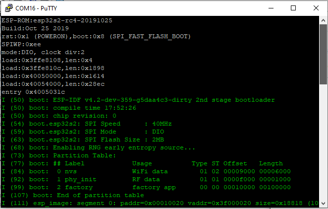
When mine starts up, it gives some basic info:


Make thanks to @unexpectedmaker for posting an informative video on the ESP32-S2 toolchain setup, including this tip on OTG pins:

ESP32-S2 USB OTG Pins   credit: @unexpectedmaker
I've adapted those notes to run my idf in WSL. There are some dependencies:

sudo apt-get install git wget flex bison gperf python python-pip python-setuptools cmake ninja-build ccache libffi-dev libssl-dev
sudo apt-get install python3 python3-pip python3-setuptools

# system-wide update to default to python3
sudo update-alternatives --install /usr/bin/python python /usr/bin/python3 10

See also the install documentation.

I also have this ESP32 install as part of my full ULX3S toolchain installer. (see upstream repo)

Thank you @i_grr for this:
One more thing, do export ESPPORT=/dev/ttyS16 once in the console session, and never have to pass -p argument to idf.py
# copy hello world
cp -r $IDF_PATH/examples/get-started/hello_world esp32-S2_hello_world

cd esp32-S2_hello_world
idf.py set-target esp32s2
idf.py menuconfig
Apparently the menuconfig will assign settings only to this project (again, thank you @unexpectedmaker for the informative video!)

To build:

idf.py build

To flash:

idf.py -p /dev/ttyS16 -b 921600 flash

To monitor (the command-line equivalent of putty):

idf.py -p /dev/ttyS16 -b monitor

Ctrl-[ to cancel

See An Introduction to Modern CMake

more to come...

Sunday, February 16, 2020

C# on the Radiona ULX3S using the nanoFramework dotnet CLR

It has been over a year since I first learned about the Radiona ULX3S development board. This is the perfect "crossover" board that has appeal for developers interested in electronics, FPGA development, and even just regular software development. With both an Espressif ESP32 and the Lattice ECP5, along with a ton of peripherals and GPIO pins - there's something for everyone here.

Radiona ULX3S from https://radiona.org/ulx3s/
The ULX3S is coming soon to CrowdSupply!

If you just want to get started with C#, see my notes here or visit docs.nanoframework.net.

A lot has changed since I first heard the name Espressif way back in 2015 and ordered this thing called a "Diymall® Esp8266 Esp-12e Serial Wifi Wireless Transceiver Module for Arduino UNO 2560 R3 Nano" from Amazon. Ooph. What a name.


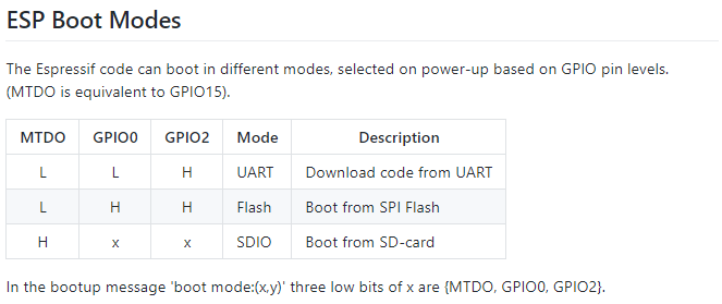
And what an ordeal it was to get that device going... I remember the convoluted process of manually holding some GPIO pin low while it powered up, and then releasing another, all with level-shifting the 5V USB-TTL on a rats-nest breadboard of jumper wires.  The "excitement' was seeing the old modem-style "AT" command prompt. Admittedly, it was pretty cool. How really surreal that was - to see the Hayes-like AT prompt for a WiFi device.

ESP Boot Modes from the ESP8266 WiKi

Indeed it seemed interesting to have modem-like commands available in such a small and inexpensive package (who knows what it would take to actually send and receive WiFi packets with AT commands!). The documentation was pretty bleak and ridiculously incomplete at the time.

Fast forward just 5 years (that's 103 in technology years) - and Espressif continues to amaze with awesome documentation and ridiculously inexpensive hardware. And the languages! I've not seen an AT prompt on any of my devices for a long time. Starting with Lua on the ESP8266, the tech community soon realized that other languages could be implemented on the Espressif hardware. Of  course, C/C++ was the first and most obvious choice for embedded devices. But then something really crazy came along: MicroPython on the inexpensive ESP8266 WiFi device. Just a few months after seeing that first AT prompt, I backed the MicroPython on the ESP8266 crowd funding project. One thing led to another and now there are many languages available, and of course the next gen ESP32 hardware platform. It was when looking at the languages on the ESP32 Wikipedia page, of all places - that I learned about a truly amazing language capability: C# on an embedded device!

I've been programming C/C++ on and off over the course of many years. At the Day Job however, my focus these days is on C# in the Visual Studio environment. That's where I am probably most comfortable and the most productive. For programming "Arduino Style" C/C++ on embedded devices, my go-to tool has been the Visual Micro add-in extension for Visual Studio. With hundreds of thousands of downloads and a solid 5 star rating, I'm clearly not alone in liking Visual Micro. I've mentioned them numerous times in prior blogs, such as this one for the ULX3S.


If you've never used the Visual Micro extension, I highly recommend giving it a try.

Back to the topic of this blog. C#. On. an. embedded. device. WOW! As mentioned above, I originally learned of this capability on the Wikipedia page. There's also a reference on the Espressif web site with a relatively simple name of "nanoFramework":

"Developers can harness the powerful and familiar Microsoft Visual Studio IDE and their .NETC# knowledge to quickly write code without having to worry about the low-level hardware intricacies of a microcontroller. Desktop .NET developers will feel “at home” and are able to use their skills in embedded systems development, enlarging the pool of qualified embedded developers. It includes a reduced version of the .NET Common Language Runtime (CLR) and features a subset of the .NET base class libraries along with the most common APIs included in the Universal Windows Platform (UWP) allowing code reuse from desktop applications, IoT Core applications, thousands of code examples and open source projects. Using Microsoft Visual Studio, a developer can deploy and debug the code directly on real hardware." --Espressif Systems
Ok, so C# on an embedded device is amazing in itself. If you've read some of my prior blogs, you've seen my interest in single-step JTAG debugging the Espressif chips. The ESP8266 in particular can be quite difficult, depending on the vendor. Still, even with JTAG working, I've never been able to get the real experience of full debugging as seen in Visual Studio with high-level language debugging, or even the Atmel Studio with the Atmel ICE for their chips.

Enter nanoFramework. This is one of the most amazing implementations I've seen in quite some time. They have the .Net CLR on an embedded device! Not just the CLR, but the fully integrated Visual Studio debugging, single-step, hover-text values and more. Getting started is pretty straightforward: first step of course is to install the nanoFramework extension from the Visual Studio Marketplace. Note there are two flavors: the nanoFramework for VS2017 and a preview nanoFramework for VS2019.

I do think their instructions are a bit overly complicated for the first time user. For one - compiling the entire framework is certainly not required to program C# on your device, yet it is featured front and center on the getting started page. I have some notes of my own on Programming the ULX3S ESP32 using C# in Visual Studio. Basically the firmware needs to be uploaded to the device, then Visual Studio needs to connect with Device Explorer.

I tweeted this video of single-step blinky in C# to show single step in action.

Beyond blinky, I was curious as to what else could be done with this framework. So how about a simple "Hello World" printed on the screen? Ha! What a twisty little passage all alike rabbit-hole that turned out to be.

First, I discovered there's currently no direct support of the SSD1331 SPI display that I am using with the ULX3S. However, there are plenty of Arduino-style libraries out there. Hm. Arduino libraries... ah yes, it is one thing to be able to write code, it is another issue altogether to actually be able to leverage the existing libraries for peripherals. All the open source code out there that allows the ESP32 to use Ardunio libraries has certainly helped the self-sustaining fire of maker interest and development. But what about C#?

I started out in the #Targets-ESP32 thread on the nanoFramework Discord. Yes, they need multiple threads for different platforms, as they also have C# working on STM32,  TI CC13x2, CC26x2, CC32xx, and NXP MIMXRT1060_EVAL boards! As my issue was not ESP32 specific, they kindly referred me to the #UI thread (UI meaning "display hardware", not the UI of the nanoFramework extension in Visual Studio). It is there that I learned a lot of great information from some clearly talented developers that very kindly and patiently answered my newbie questions.

I only recently started using Discord. I think I like gitter channels more, but both seem to be weak for linking to specific comments of interest. Part of this blog is for me to gather up the key tidbits all in one place. Be sure to check out the ULX3S gitter channel, too.

I learned quite a bit about the SSD1331 display during a exchange with emard in ULX3S issue #8. For the nanoFramework here I started with a known-working project, my ULX3S Visual Micro SSD1331 Display Example. In particular, the key pin numbers:

// working ULX3S  
#define oled_csn  17 // aka cs - chip select
#define oled_dc   16 // aka ds aka a0 -  SPI data or command selector pin
#define oled_resn 25 // aka rst - reset
#define oled_mosi 15 // aka mosi - data
#define oled_clk  14 // aka sclk - clock
#define oled_miso -1 // 12 not used

from the FPGA perspective:

N2 to N3 for oled_csn /CS  to wifi_gpio17 (GPIO17)
P1 to L1 for oled_dc /DC   to wifi_gpio16 (GPIO16)
P2 to E3 for oled_resn/RES to wifi_gpio25 (GPIO25)
P3 to J1 for oled_mosi/SDA to sd_cmd      (GPIO15)
P4 to H2 for oled_clk /SCL to sd_clk      (GPIO14)

See also this code on the espressif/arduino-esp32 repo for VSPI and HSPI initialization and pins:


void setup() {
  //initialise two instances of the SPIClass attached to VSPI and HSPI respectively
  vspi = new SPIClass(VSPI);
  hspi = new SPIClass(HSPI);
  
  //clock miso mosi ss

  //initialise vspi with default pins
  //SCLK = 18, MISO = 19, MOSI = 23, SS = 5
  vspi->begin();
  //alternatively route through GPIO pins of your choice
  //hspi->begin(0, 2, 4, 33); //SCLK, MISO, MOSI, SS
  
  //initialise hspi with default pins
  //SCLK = 14, MISO = 12, MOSI = 13, SS = 15
  hspi->begin(); 
  //alternatively route through GPIO pins
  //hspi->begin(25, 26, 27, 32); //SCLK, MISO, MOSI, SS

  //set up slave select pins as outputs as the Arduino API
  //doesn't handle automatically pulling SS low
  pinMode(5, OUTPUT); //VSPI SS
  pinMode(15, OUTPUT); //HSPI SS

}

I tried to use the existing SPI capabilities of the nanoFramework, but I was unable to get the display to cooperate. Nothing happened. But why?

This is where more serious hardware debugging tools are needed. One method I used in the past to debug some serial port communication problems - involved a Digital Storage Oscilloscope (in my case, a Rigol DS1054z). Even though that one is relatively small as oscilloscopes go, it was at my workbench and I was working at the kitchen table (and ok, the workbench needs to be cleaned up an organized). Not only inconvenient, but also perhaps not the most practical (power cord, size, etc). Although my serial decoding was an interesting exercise on the oscilloscope - what I really needed is a logic analyzer.

It was well over 5 years ago that I first started using the Saleae logic analyzer software. The cool thing here is that it is a computer-based debugging tool. Whereas the oscilloscope is an oscilloscope all on its own, complete with its own power cord and display - the Saleae is just a USB peripheral. It doesn't even have a wall-wart power supply: just a USB connection and logic probes.

Sure enough - after a ridiculously long time trying to figure out the display problem with software, the logic analyzer instead made the problem abundantly obvious: nothing was happening as the D/C (data command) pin. I was hoping that somehow the SPI driver would have just "known" how to control the bus for the display during NativeInit. Silly me. Of course not. Nope.


I opened this issue to implement more flexible SPI pin definitions, in particular something to manage that D/C pin. @AdrianSoundy responded with:
"The DC and Reset pins are not part of the SPI bus. They are specific to the displays. You have to create separate gpio pins for those functions."
Hm. Well, yes, I guess that is technically true. Still, I wanted to see if I could get my SPI  display to work in C#, so I took the advice and wrote my own DC-pin-controlling code to manage the data/control line, and let the native drivers handle the actual data transfer.

I created this nanoFramework SSD1331 example to manually bit-bang the SPI bus. As of the date of this blog, there's not a lot there. I leveraged the Adafruit SSD1331 C++ library to create my own limited C# OLED SSD1331 class library. I also created another class library project, this one an Arduino-style nanoFramework "pins" helper to allow the use of the familiar pinMode and digitalWrite functions when converting the Adafruit library to C#.

It is a bit of a mess at the moment, but it does have the capability of initializing the display and poking some pixels into place. It doesn't sound like much - but again, doing this from C# in Visual Studio is what made it really quite cool. I had this little victory tweet at the end of that weekend:


Drawing a line is one thing... drawing it quickly, well that's another. After the excitement had warn off (ok, it was just a blue line)... I realized just how slowly the pixels were being drawn. Why? Did I mention the little twisty passages? Yes, this rabbit hole goes much deeper.

To start, let's go back to the known-working SPI display example. See also this blog where I go into more detail with that example.

Again, there's nothing like a logic analyzer to see what's going on with the voltage levels of ones and zeros on the wires. Looking at the source code, the SPI bus for the display gets interesting at startup time, or specifically during Adafruit_SSD1331::begin - where initialization bytes are sent to the display:


void Adafruit_SSD1331::begin(uint32_t freq) {
    initSPI(freq, SPI_MODE0);

    // Initialization Sequence
    sendCommand(SSD1331_CMD_DISPLAYOFF);   // 0xAE
    sendCommand(SSD1331_CMD_SETREMAP);          // 0xA0
#if defined SSD1331_COLORORDER_RGB
    sendCommand(0x72);    // RGB Color
#else
    sendCommand(0x76);    // BGR Color
#endif
    sendCommand(SSD1331_CMD_STARTLINE);  // 0xA1
    sendCommand(0x0);
    sendCommand(SSD1331_CMD_DISPLAYOFFSET);  // 0xA2
    sendCommand(0x0);
    sendCommand(SSD1331_CMD_NORMALDISPLAY);   // 0xA4
    sendCommand(SSD1331_CMD_SETMULTIPLEX);  // 0xA8
    sendCommand(0x3F);     // 0x3F 1/64 duty
    sendCommand(SSD1331_CMD_SETMASTER);   // 0xAD
    sendCommand(0x8E);
    sendCommand(SSD1331_CMD_POWERMODE);   // 0xB0
    sendCommand(0x0B);
    sendCommand(SSD1331_CMD_PRECHARGE);   // 0xB1

...etc


This is where I had a chance to try out my new Saleae logic analyzer. It's funny how once you buy something, you start noticing other people that have that same "thing". I noticed that @GregDavill had posted something on Twitter with his Saleae - and so I commented on it. His reply was crazy! I don't think I'll be using mine as a coaster anytime soon LOL. So here's my new Saleae, sans mug, hooked up to my Radiona ULX3S:

ULX3S with SSD1331 display on a breadboard with Saleae Logic Analyzer
In order to most easily connect the logic analyzer, I disconnected the display from the main ULX3S board and plugged it into the breadboard. Here, I would have preferred that the Saleae had male connector pins instead of female, but a few short M-M jumpers to the rescue.

I did buy my own Dupont crimping too la few years back, so I will probably make my own Saleae male-pin probe set for breadboards. The only think needed is some wire and a Dupont header kit such as this one on ebay.

So back to the setup: Not completely intuitive is the trigger and decoding of the SPI signals. The first thing is to setup the start of capture based on the falling edge of the clock:


The next is to tell the Saleae software *which* pins are being used for decoding. First select the SPI decoder on the right side of the app:


Next, click on the little gear and "edit settings" to select which channels are which SPI pins:


The good thing is that if you don't need to change protocols, the software remembers this even after uninstalling and re-installing new software. So until you change debugging projects, the setup of the logic analyzer stays consistent.

From a software perspective, we just simply expect the bytes to be sent. But to actually see what's going on, the logic analyzer is indispensable:


Here we can see the same hex codes in the Salaea decoded from the logic analyzer probes as seen in the code segment, above. Setup of the decoder in the software was also vastly easier than the serial decoder mentioned above on my oscilloscope. The first byte sent on the SPI bus is 0xAE, the command turn turn the display off during initialization. How cool is that?

Although the Salaea software is not implemented with the proper Windows UI (banner toolbar across the top, File-Save, Help-About, etc)... for the most part it is quite easy to use and intuitive. One of the less-obvious features is that you can double click on the decoded values in the lower right, and the display auto-scrolls and auto-scales to the trace for that value. Very nice.

Once I had a benchmark of sending a byte of SPI data in under 8 micro-seconds, let's see what happens when manually bit-banging the pins from C#. Here's the code to send an SPI byte:


        private void spiWrite(byte b)
        {
            for (byte bit = 0; bit < 8; bit++)
            {
                if ((b & 0x80) > 0)
                {
                    SPI_MOSI_HIGH();
                }
                else
                {
                    SPI_MOSI_LOW();
                }
                SPI_SCK_HIGH();
                b <<= 1;
                SPI_SCK_LOW();
            }
        }


This is pretty straightforward and almost identical to the Adafruit C/C++ code in their SPITFT library (minus the hardware-specific conditional compile directives) that I based my C# code on. See also the spiWrite() in esp32-hal-spi.c.

Next, I tried to use the built-in nanoFramework SPI driver, but manually control the D/C line.


private void WriteCommand(byte command)
        {
            _buffer1[0] = command;

            // the time between the next two statements is a whopping 0.3ms
            _DS.Write(GpioPinValue.Low);
            _DS.Write(GpioPinValue.High);

            // here we manually bring DS low
            _DS.Write(GpioPinValue.Low);
            _spi.Write(_buffer1); // all 8 bits in about 54uS
            _DS.Write(GpioPinValue.High);
        }


Here's what it looks like on the logic analyzer:


Notice in particular the vastly longer delay in switching the D/C line as compared to the bits sent during the native _spi.Write(). There's nearly three-quarters of a millisecond window for the D/C line, but only about 54 microseconds to send the entire 8 bits of data:


When I posted this information on the Discord channel, @terryfogg suggested that I review a similar example being worked on. From what I could tell, it was VSPI with a different set of pins and also confirmed that C# is just too slow for this kind of, so instead this was using native code. Ah yes, the twisty little passage - the Rabbit hole goes on to another whole level: calling native code from C# on an embedded device.

The next level of complexity? Interop of course. To get started, there's a pretty good tutorial on Interop in the .Net nanoFramework. Yes, interop of course pretty much screws the entire concept of managed code, but with the benefit of vastly better performance. Hm. See the links at the bottom of this page for more information on calling unmanaged code from C#. I think that's probably a whole topic in and of itself. Stay tuned...


Full disclosure: I purchased the Saleae Logic Pro 16 at a substantial discount since I (sadly) don't do this fun stuff for a living. Saleae has a "Electronics Enthusiasts (non-commercial use)" discount. My primary motivation was the USB3 sampling speeds of up to 125MHz to be used as I dig deeper into the ULX3S FPGA capabilities. The discount of course made all the difference for my hobbyist budget. In fact, there's an "Enthusiast Discount Extreme Edition" that I hope to qualify for with this blog entry.

I purchased the ULX3S early last year from Goran after reading about it on Hackaday and sending an email. Although I am listed as one of the members of the Radiona CrowdSupply team, I am not employed by Radiona, nor do I receive any financial compensation from them.

All opinions expressed here are my own and not representative of my employer.


Resources, Inspiration, Credits, and Other Links:

Friday, January 31, 2020

Embedded C# on the ULX3S ESP32

My January efforts have focused on writing C# on an embedded device. Yes, you read that correctly: C-Sharp. On and Embedded device. WOW! In my case, the ESP32 onboard the Radiona ULX3S. This is all thanks to the clever folks working on the nanoFramework.

I have an interim walk-though on my SSD1331 GitHub branch here:

https://github.com/gojimmypi/ulx3s-examples/tree/SSD1331/nanoFramework

I'm currently working on figuring out how to compile the interpreter. See the Discord discussion.

This is a work in progress, so come back for updates.

Saturday, June 1, 2019

ULX3S and Visual Micro in Visual Studio 2019

This blog is a walk-though using the Visual Micro Arduino IDE in Visual Studio 2019 to program the ESP32 on the Radiona ULX3S. For more information on the ULX3S see my Day 1 intro, Using ujprog on WSL or MinGW, and Notes on ulx3s FPGA: Yosys, Verilog, VHDL, vhdl2vl (Convert VHDL to Verilog). Here's the ULX3S with the SPIDriver.

ULX3S with SPIDriver board
There are some brief online instructions for manually installing Visual Micro, or you can follow along here, using the VisualMicro example for the ULX3Son GitHub:

In Visual Studio 2019, click on Extensions - Manage Extensions.


Select "online" in the left pane and type "Arduino" in the search box:


Note the 5 stars reviews from hundreds of users. Yes, it is a very cool extension. :)

Next, click on the "Download" button. You'll need to restart Visual Studio 2019.

Be sure to wait for the VSIX installer screen! The first time I did this, I simply launched Visual Studio right away, and the Visual Micro Extension was no where to be found! Before launching Visual Studio, you should see this screen:


Then after a warning about system changes, this prompt:


Click the "Modify" button to continue. Upon completion, there should be a message "Modifications Complete"


When Visual Studio is next launched, click on "Create a new project"


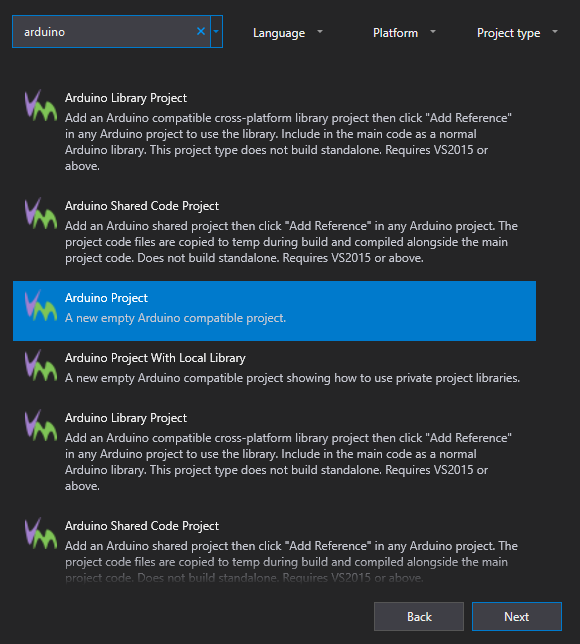
There are many project types, so type "Arduino" in the search box:


Select "Arduino Project" and click the Next button.


Give the project a name, and a location to store it. In this case, I am saving it in my ULX3S examples fork directory, to create a pull request to the official ULX3S Examples.

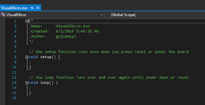
After clicking  the "Create" button, a familiar Arduino-style code template is created, with the setup() and loop() functions:


So that's the easy part. Now things get more interesting. The ESP32 on the ULX3S sits behind the FPGA chip. This means the only way to program the ESP32, is to have code on the ULX3S that performs a "pass through" function of external physical pins to the ESP32 pins through the FPGA.

schematic showing the ESP32 to FPGA connections


Fortunately, the ULX3S typically ships with the pass-though FPGA app already loaded. If not, the FPGA source code can be found here. Note there are three different versions: the Diamond VHDL that emard wrote, a Diamond Verilog that I converted from emard's VHDL, and finally an Open Source Verilog version that uses yosys and nextpnr. (hm, it looks like from the most recent comments I need to get the open source version working properly - I'll need to look into that)

If you are not ready to jump into the synthesis of FPGA bit files yet, you can use the passthru image file passthru_ulx3s_v20_12k.bit and load it onto the ESP32 using the ujprog tool. If you don't feel like building your own, there's a copy of both the bin directory.


if NOT EXIST c:\workspace mkdir c:\workspace
git clone https://github.com/gojimmypi/ulx3s-examples.git c:\workspace\ulx3s-examples
c:
cd \workspace\ulx3s-examples\VisualMicro\bin\
.\ujprog.exe passthru.bit


If "Cannot find JTAG cable" is encountered, remember that WSL is still not supporting native USB drivers. If you are using the Windows executable version and you see that message try changing the ULX3S drivers back to FTDI particularly if you don't see your ULX3S in the Ports (COM & LPT) container in device manager. WSL can be finicky, and even have different results whether executing from a Linux directory or DOS (e.g. /mnt/c/). And yes, native Windows executable files can be launched from WSL! cool.

Visual Studio seemed to have defaulted to all the correct values for me (I'm note sure if perhaps it remembered values from Visual Studio 2017) Here they are for reference:


Of particular interest is ensuring the proper COM port is selected, near the bottom of the settings list. I didn't see the actual ESP32 device listed (WROOM-32), so I used the ESP32 Dev Module setting.

Once the pass through FPGA binary has been successfully uploaded, the simplest way to compile and upload the Arduino code via Visual Micro is to press F5 or the big green "start" button! That's it!

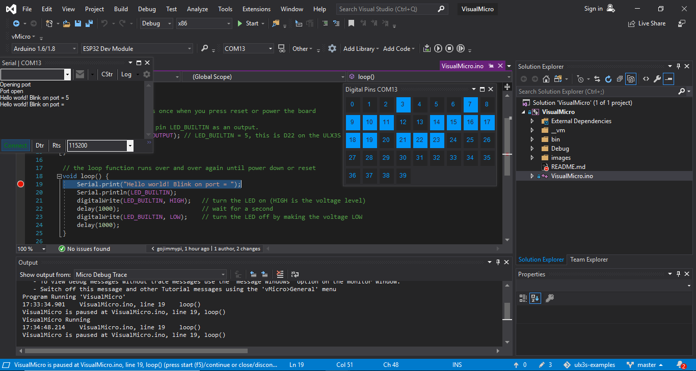
Note that one of the amazing things about the Visual Micro IDE, is they have implemented a debugger that does not require a hardware JTAG device! Here's my ULX3S ESP32 paused at a breakpoint:


Now onto that SPI Driver! Stay tuned for more....


Sunday, December 30, 2018

Favorite Gizmos of 2018

As the end of 2018 approaches, I thought it might be nice to share a list of some of my favorite electronic gizmos. In no particular order:

It's difficult to have any gizmo list without the Raspberry Pi being listed. So voila, let's move on.

One of my favorite gizmos is the DPS5015. In and of itself, perhaps not super interesting: your basic Programmable Supply Power Module. However it was the first commercial product that I "re-purposed" and learned a lot of hardware hacking as noted in my blog from 2017.


I think some of the most amazing devices are the SDR gizmos, such as the NooElec NESDR Smart Bundle on Amazon. (On my wish list is the Lime Micro SDR). Last year I wrote a blog on streaming SDR information directly to an OpenWRT router. I also used my SDR during development of my LoRa button-pushing project (see below).

Also cool, although also not new for 2018 - is the M5Stack series of ESP32 modules, complete with enclosure and display.

I wrote a blog about the M5Stack LoRa range, as well as a blog about my LoRa-GPIO project (pushing a button from afar). A prototype M5Stack that had both an AVR and ESP32 device turned out to be quite the educational experience as noted in my Serial Port Debugging blog, featuring the Rigol Oscilloscope Protocol Decoder. (see also Dave's EEVBlog Review of the DS1054z)

Early in the year, I bought an inexpensive Altera Cyclone IV EP4CE6 FPGA Development Kit and wrote a blog about it. This was my first experience with FPGA and proprietary tools (Quartus).

Cyclone IV FPGA Dev Board
I think one of the most significant new gizmos of the year was Luke's tinyFGPA BX. Be sure to follow @tinyFPGA on twitter. Learning to program an FPGA is something that I've been wanting to do for a long time. Luke - along with a bunch of other FOSS advocates, such as FPGAwars - have finally made it easy and inexpensive for the newbie. There's some really great BX getting started information. One of the coolest FPGA programmers has got to be Icestudio.

Late in the year, [@esden] introduced another cool FPGA device on Crowd Supply called iCEBreaker. Some folks lucky enough to attend conferences have been able to obtain theirs... others (including me) will not have them until delivered until next summer.

Finally - at the very end of the year, there's also the Fomu Crowd Supply project - An FPGA board that fits inside your USB port! (also due next year)

There's an excellent web-based Verilog editor and simulator online from the folks at 8-bit workshop. Be sure to check out their new book Designing Video Game Hardware in Verilog, as well.

Once I get a handle on FPGA programming, I plan to do something with this AD/DA board I found on ebay. (using AD9280 & AD9708)

At the very end of the year, I found the XGecu TL866II Plus USB Programmer from the XG Autoelectric folks (see also xgecu.com), thanks to @tinycompblabla.  At only about 50 bucks, it is considerably less expensive than something like the elnec or dataman. I'm looking forward to receiving it in January.

On the topic of component testers, is the AVR-based M328 Transistor Tester project. (source code here). This is really a quite clever device that automatically detects what component is connected, then indicates whether it is good or not. For things such as transistors, basic key characteristics such as gain and Vbe are displayed.


M328 Transistor / Component Tester

See also the ISP pins in case you want to get creative with your transistor tester.

One of the cool gizmos that I recently purchased is the Arduino MKR WiFi 1010 (also available from Amazon). Atmel SAMD21, ESP32 WiFi, ECC508 Crypto-Authentication, all in one place! This gizmo is so cool, I wrote an entire blog about SWD programming the Arduino MKR WiFi 1010 with the Atmel ICE.
Atmel ICE and MKR WiFi 1010
In the Fall of 2018, I found this cool SPIdriver dev board on Crowd Supply. This too, was so cool that I wrote an SPIdriver blog about it. Note that the same guy has an upcoming and similar I2C driver project, as well - that looks just as cool.

Although perhaps not a gizmo in the pure electronic sense... I did buy myself an inexpensive 3018 Pro CNC machine - as CNC programming is also something I've always wanted to learn. I need to get my thoughts together and put all that information in a blog entry soon. Stay tuned.

This blog is still a work in progress... if you think of any gizmos that I should look at and perhaps add to this list, let me know via twitter or @ gmail.

Wishing everyone health and prosperity in the coming new year.

Cheers.


Sunday, July 15, 2018

Pushing a button. From afar. With LoRa.

This blog entry is about pushing a button. Seems simple enough, eh? Except when the button you want to press is very far from where you are physically located... say, when there's a remote gate control well out of sight and out of range for the remote. Oh, and it is also too far to have any network connectivity. What to do?

My plan is to use LoRa to communicate from an M5Stack console to a distant LoRa32u4, each equipped with a LoRa module; essentially push the button of the remote from afar! The actual pysical button push on the M5Stack will essentially be "sent" (via LoRa message) to the remote 32u4 which will then trigger the actual remote control transmitter. The working prototype is shown here:


How to get there: The first thing needed is to disassemble the remote and determine how it normally works. The remote I am using is a Somfy TR2 similar to this one that can control two different devices. Upon disassembly, the first thing we see is those two buttons each with 4 pins. The buttons appear to be very similar to this Grayhill Gull Wing 95C06C3RAT at Mouser as documented here. Note that although there are 4 pins, it is simply a SPST switch:

Photo credit: Grayhill spec sheet

I confirmed both visually and with an ohmmeter that indeed I have a similar switch and proceeded to connect some external wires to it:

Somfy remote switch wiring

If you look closely, I took the time to wrap the wire around the pin of the switch to make a good mechanical connections, while being careful not to touch any other circuit. It would probably be a good idea to use some hot melt glue and affix the wires to the pc board.

Here, Green is a ground (all 4 pins, 2 from each switch); Orange is BP1 and Yellow is BP2. The top of the battery is labeled as being the positive side. The entire metal surface here is at 3.3V:


This turned out to be an extremely handy arrangement for me: the entire device could essentially be the "load" for an NPN transistor circuit!

Putting an ammeter between either the orange or yellow pins to ground, I found about 0.3mA that would otherwise flow though the button (or a transistor).

Looking at the specs for the 2N3904, the max collector current is a whopping 200mA  max, well over a couple orders of magnitude for what we'll need:


And for a collector current of (we'll round up) to 0.5 mA, we'll have a minimum gain of around 60 to 80 (let's pick a gain of 70 for discussion-sake):


We'll need a base current of around  (0.005A / 70) =  0.0714 mA;  For the current-limiting base resistor, we'll thus need: 3.3v / (0.0000714) ~= 40K ohms. I didn't have a 40K handy, but I did have a bunch of 20K ohm resistors laying around, so I'll use that. It is still well within spec, and will certainly account for any gain drift or degradation.

Our button-pressing supplement thus looks like this (shown for BP1, but the same for BP2):
Note that this circuit will allow our 32u4 to control the remote via a GPIO pin. Fortunately the remote is also smart enough to turn itself off - if for some reason the button remains pressed so that the battery does not drain (such as being poked by your keys in your pocket). In our case: regardless of the state of the pin during power up (or application crash) the battery will be preserved.
The manual prototype looks like this:


Note the red wire to drive the base of the transistor is stuffed into the battery holder for the picture. Once in operation this red wire will instead be the GPIO output from the 32u4.

Next, we need to make sure the remote is actually working! As mentioned in my previous blogs on M5Stack LoRa Range Issues as well as this fun project using OpenWRT on EA3500 with RTL-SDR Stream, I have an inexpensive NooElec SDR, that is simply amazing - particularly given the price! With this hardware, and the some software, we'll be able to "see" the remote signal.

The last time I used Cubic SDR, it was working fine. Today? Nothing. Erg. Gotta love Windows. App starts, no complaints, but no signal. A little bit of googling, and there's the Quick Start Guide. First thing I noticed was mention of my old friend, zadig. Sure enough: during one of the the Windows updates, the default driver was changed for some bizarre reason. Here's the screen just before correcting it:


And tada! Exit Cubic SDR (no need, at least for me, to reboot computer)... relaunch Cubic SDR app... then pressing Start for my RTL2832U device:


The waterfall immediately starts! Press the button on the remote a few times, and we can see the pulse at about 433.5 MHz. Notice the messy side-band noise, as well as someone else continuously transmitting at about 432 MHz:


I have the source code for all this on GitHub here: https://github.com/gojimmypi/LoRa-GPIO (note there are also Development and M5-RadioHead branches, but after a bunch of GitHub fussing, I think the master branch is now up to date). The projects are VisualMicro extensions to Visual Studio, but I suspect the Arduino code would work just fine in the Arduino IDE.

More to come...

Tuesday, March 13, 2018

The Magic of Visual Studio and GitHub Integration

The more I use Visual Studio 2017 and the integration with GitHub, the more I am amazed at just how well this all works. I'll use a real-world walk-through with some Espressif ESP32 Arduino code that I am using on my M5Stack to show how really useful this is.

First, note that I have a couple of add-ins installed (Tools - Extensions and Updates). In particular the Arduino IDE for Visual Studio and the GitHub Extension for Visual Studio.


I was reading this thingpulse blog entry on reducing ESP32 power when I noticed the line:
WiFi.forceSleepBegin();

Hmm... interesting. But when I tried to use that, it seems to not be implemented for me:


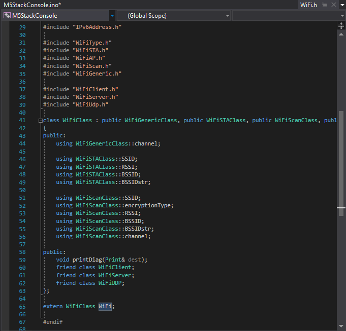
So here we can right click on WiFi and Go To Definition:


And sure enough.. the WiFi.h file opens... but as a "soft" open tab on the right, instead of the regular solution file on the left; hmm. there's no forceSleepBegin() in the header. Let's see if we can find out more.


It gets more interesting, as now we can right click on the WiFi.h tab name and select Open Containing Folder:


So here I can see which of the several (in my case Arduino or ESP32) WiFi libraries are actually being used in this project. In the path we see the ESP32 library is being referenced:


Now.. this directory was installed via a git clone command some months ago.

Even more cool, is we can right-click on Windows Explorer and Open in Visual Studio. (yes, going back!) Be sure to click on white page in the Explorer file list, and not on a specific file. Otherwise only that single file will be opened.


Note how the ~\src directory is opened in the solution. Looking closely, there are little lock symbols next to each file! I didn't do anything to set that up. It just works!


Yes, those little locks say "this is a file under source control and has not been checked out nor edited".

Next, to really see the magic, click on the Team Explorer tab (or View - Team Explorer).


Look! A Welcome to GitHub for Visual Studio message. It just knows that this subdirectory has a parent directory somewhere above that has the git clone repository information. How cool is that!?!

Click on the Sync Button/Tab and we can see the incoming commits, LIVE from GitHub!

Here we can press the Fetch link to just bring in the historical information, but not change our local files.


Want something else? Click on the master Branch text/link, to view the other branches:


Double-click to select a different branch. All the usual git commands apply, so git stash is probably your friend here. (unfortunately manually from command line, as far as I know)

Sadly, the "Search Work Items" does not seem to work for me; I cannot type anything there. That will soon be a Very Cool feature.

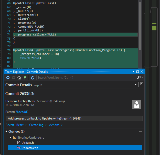
We can however, right-click on commit items and compare & see what changes by pulling each commit:


All from the comfort of the Visual Studio UI. How really awesome is that!?! :)

Close the yellow welcome message banner and we can see exactly where this repository lives on GitHub. Press the little home icon any time in Team Explorer to return to this view:


Click on the repository link and the GitHub web page for the repository (in this case Espressif Aduino repository on GitHub) opens in your default browser.

As a suggestion, there are probably some files that should be added to your .gitignore file. Simply going though this exercise creates some files that you probably don't want to push back to the repository and may interfere with pulls. Click the Changes tab/button on the Team Explorer home to see what's been added:


These will of course interfere with selecting other branches, etc.

Overall this is really quite cool. The developers creating Visual Studio simply rock. :)

There's a ton of other cool stuff going on. Be sure to check out The Visual Studio Blog and the Visual Studio conversation in the Gitter community.


Other links:

Find gojimmypi at gojimmypi.github.io

I'm currently working on my new blog home at  gojimmypi.github.io After implementing a variety of features such as dark mode , syntax hi...