Showing posts with label Limit Switch. Show all posts

Monday, October 12, 2020

CNC 3018 Limit Switch End Stop Mounts (3DPrinted)

This is a continuation of my prior blog: The road to CNC3018 Limit Switches

Update: I've migrated my blog to GitHub pages, here and posted the STL files here.

These parts that I custom designed are for the CNC3018 (specifically the CNC3-3018Pro) Desktop CNC Engraving Router such as the one I purchased from Twowin Tools on AliExpress. Some of these mounts may be applicable to other CNC Routers as well. ymmv.


All of the designs here are for the relatively common Makerbot limit switch available on Amazon, eBay, AliExpress, etc...

There are certainly less complex implementations of limit switches.

WARNING: CNC Machining, even on a small desktop unit is inherently DANGEROUS.

I'm a software engineer at the Day Job, with relatively minimal mechanical engineering experience. This project is also my first experience with Fusion360. Although I've gone through (an embarrassingly large number of) iterations trying to take into account a surprising number of factors - there are probably still problems. DO NOT RELY ON THESE MOUNTS FOR PERSONAL SAFETY. There is no guarantee of proper operation or reliability. 

WEAR EYE PROTECTION AT ALL TIMES.

For installation, I wanted to minimize any additional machine tooling: no drilling, cutting, or other modifications are needed to mount these switches.

Parts Needed:

  • 6x Switches: a pair for each axis end limit: X, Y, Z.
  • M3 x 8mm screws.

Optional:
  • Assembly tools such as a quite handy 2.5 MM Ball-Hex (allen) driver. The ball-end is just too cool for screwing in M3 nuts from an angle.

  • Opto-isolator, such as the CNC Optical Limit Switch Isolator - GRBL on Tindie. Note that TWO of these boards may be needed to cover both end limits for some machines. This is clearly illustrated in the schematic that I should have studied more closely (but who would want a limit in only one direction?). As it turns out, I was "lucky" in that both ends of each axis are tied together on the PCB anyhow. So one board should work just fine for my desktop CNC:


Axis Designation

The notation in Fusion360 XYZ, Red Green Blue is followed:


These parts are all printed with Prusament PLA (silver) on a Prusa I3 MK3S kit with the Double-sided Textured PEI Powder-coated Spring Steel Sheet using mostly default settings for 0.15mm Quality, 15% infill and the "brim" checkbox in the PrusaSlicer with the exception that I increase the bed temperature to 65C for the first layer: 

X-Axis (red)

The X-Axis on the CNC3018 is the left-right worm gear holding the engraver motor. Thus the motor moves in the X and Z directions.

My final design for the X-Axis end-stops uses the black Bakelite sides as the stop for the actuator.

The switches are mounted on a pair of symmetric clip-on brackets. One is as shown: 

X-Axis Switch Mount

  1. The wrap-around clip that holds the bracket in place.

  2. Holes for 5.5mm nuts. The fit is a bit tight to make assembly easier. It may be useful to first thread a screw to pull the nut into the hole.

  3. Wire routing channel.

  4. Alignment holes for the "chimney" portion of the wire routing channel extension.


  5. Continued wire routing channel.

  6. Cutout for wire exit.

  7. Nubs to snap into pre-existing hold in the side of the motor mount.


Here's the as-seen, design view of one of the mounting clips with the chimney:

With an additional X-Axis Clip-on Bracket, the actual assembly looks like this:


Y-Axis (green)

The Y-Axis end-stops are located underneath the plan of the the moving table. Two assemblies are used: one on each side of the router table. The design is such that the switch is positioned underneath the table to minimize debris dropping into what could have otherwise been considered a bucket in earlier designs. This was one of the many things not considered during design, but abundantly obvious once viewed in place.

There are a total 7 parts for each of the Y-Axis mounts. Although one could certainly buy mounting hardware, 4 of the printed parts are the pair of nuts and bolts:


Printing nuts and bolts is a learning opportunity (including paying attention to left or right-hand threading). The fit is not super great as-printed. I used this as an excuse to buy a metric tap and die set. These specific ones are designed as M8X1.25

Other than the 4 parts for nuts and bolts, the remaining 3 parts for the Y-Axis are the actual switch mount, lid and limit stop. The stop is a vertical thin tab designed to be break-away in case of mishap, instead of destroying the bracket housing the Y-Axis electronics:

The vertical tab stop is not only thin, but it is also printed parallel to the print bed, making it even more weak. It should only be strong enough to trigger the switch.

The body of the Y-Axis switch mount Body is considerably more complex:


  1. Through-holes for mounting the PCB for the switch.
    (2x) 10mm M3 screw and (2x) 5.5mm nuts.

  2. Posts with a snap-in nub for the other 2 holes in the switch PCB.

  3. Bumps to help catch and hold the lid from the sides.

  4. Another bump to hold the lid in place.

  5. Opening for wire exit.

  6. Narrow channel for wire routing.

  7. Mounting holes to mount to side rail. 
    (2x) 8mm M3 screw and (2x) T-Slot nuts.


    The final part of the Y-Axis end-stop is the Lid:


  8. Catch for the bumps on the base, (#3) above.
    s
  9. Rear catch for #4 bump from above.

  10. Wire hold-downs.

  11. Window for switch trigger arm.
The complete, rendered Y-Axis mount Body and Lid:


A complete set of the above Y-Axis parts is used both on the left and right sides for min / max limits.

(TODO: which is which?)

It's probably best to mount the PCB inside the switch housing and install the lid before mounting to the side rail with (2x) 8mm M3 screw and (2x) 5.5mm nuts.


Z-Axis (blue)

There are 4 main components for the Z-Axis: an upper and lower end limit clip, and a 2-part switch mount. All attach to the motor mount with snap-on, press-fit.

The first part is this lower limit clip:


  1. The sides extend back fairly far. They are thin here to minimize any wasted travel distance range in the X direction (the motor mount otherwise travels right up flush with the Bakelite sides.

  2. Little round nubs catch in pre-existing holes on the motor mount.

  3. An extension is providing to distance the clip from the actual switch lever.

    The next part is the upper clip used for the vertical limit:


  4. Mounting brackets to snap onto the vertical Z-Axis motor spacers.

  5. Spare cutting bit holder. (beware the bits are extremely sharp: the protective cover for them typically protects the bit, not your fingers. Yes, I learned this the hard way. Twice. The first time, I didn't even know how I cut my finger!)  TODO: design a cover.

  6. Not visible in this photo is a little bump that hits the upper Z-Axis switch.

    Switches are mounted with this two part assembly. The first part snaps onto the motor mount:


  7. Mounting Holes to attach the second part that has switches mounted. (see below)

  8. Clearance for the upper clip.

  9. Clearance for the lower clip.

  10. Upper nub to latch housing onto motor mount.

  11. Part of housing "wraps around" front of motor mount here.

  12. Unnecessary material removed.


  13. Posts with a snap-in nub for the other 2 holes in the switch PCB. (upper limit)

  14. Posts with a snap-in nub for the other 2 holes in the switch PCB.(lower limit)

  15. Through-holes for mounting the PCB for the switch. Aligns with holes in first part, the inner housing described above. This is for the lower limit switch.
    (2x) 10mm M3 screw and (2x) 5.5mm nuts.

  16. Through-holes for mounting the PCB for the switch. Aligns with holes in first part, the inner housing described above. This is for the upper limit switch.
    (2x) 10mm M3 screw and (2x) 5.5mm nuts.

  17. Unnecessary material removed.

  18. Ridge to hold snap-on cover (TODO: design Z-Axis switch cover)

Both Z-Housing Mounts, rendered together as a single assembly:


And so I guess in the end, yes: this is a rather overly complex design for something as (seemingly) simple as CNC limit switches. Alas this is 2020 and I have plenty of time at home to learn all these things that I've wanted for so long. For a software guy like me - it is really quite amazing to draw something and have it actually end up as a physical thing, all from the comfort of my home.


If you've read along this far (hey! thank you, I'm glad someone is interested) ... and if you have a CNC machine like the one described above but do not have a 3D printer, I have a bunch of initial prototype parts that with a bit of TLC (read: they don't fully work; time needed to sand, cut, or otherwise modify and adjust) ... that could probably be adapted to function. I'm willing to ship them anywhere in the USA for free, and perhaps anywhere in the world, depending on actual destination and cost. It's a shame to throw them away and I don't know what I would do with them otherwise. So if the prototypes can go to a good home, let me know. My blog name at gmail works.

See my next blog post on CNC 3018 Makerbot Limit Switch Wiring.

As always: I am not specifically recommending or endorsing any of the product links in this blog. None are ads, or "affiliate" links. These links are included from my personal experience, "notes to self" and for reader convenience only. If you, too, are ridiculously tired of excessive ads, check out The pi-hole.


CNC 3018 Makerbot Limit Switch Wiring

This is a continuation of my prior blog on limit switch mounting hardware design for the CNC3018.

There are plenty of resources on various limit switch wiring. As with most information on the internet: some is good, some not so good. One place to start for the desktop CNC is the gnea/grbl wiki: Wiring Limit Switches.

One of the first things to note is the Woodpecker board is designed such the the default switches are expected to be NO (Normally Open, High); The limit is triggered by pulling the signal low (short to ground).  This is unfortunate, as switches will typically fail in the open position. Worse: Perhaps they even become disconnected and stay apparently open during a limit-exceeded condition.

I ordered these switches from ebay. There are similar ones on Amazon. Here's a switch installed in the Y-Axis mount that I designed in Fusion360:


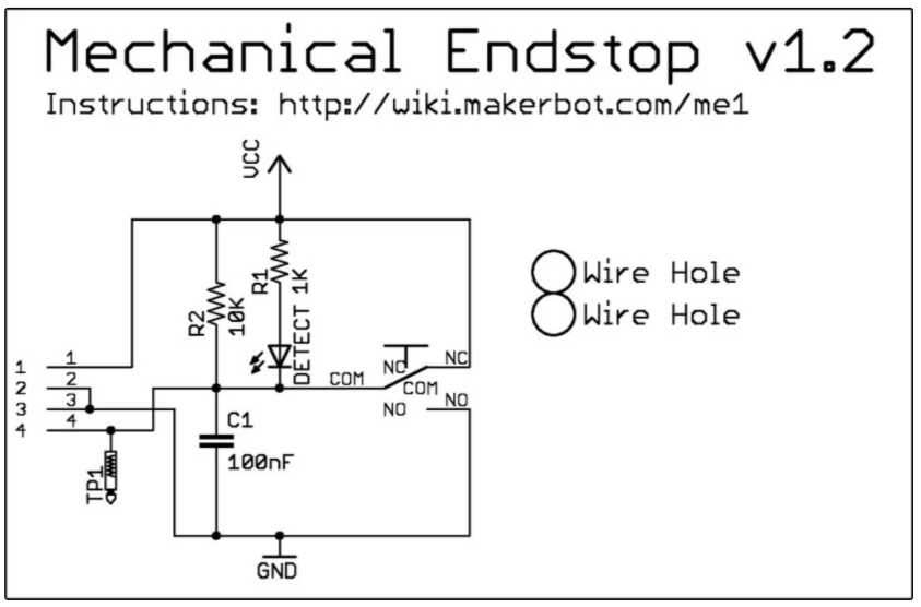
Although there's a wiki link on the board schematic, it has long since disappeared from the internet. Fortunately I was able to recover some key files from the wayback machine, and copied them here for reference (next 5 images credit: Makerbot):


Interface description:


The PCB layout:


Bill of materials:

PCB Render; "The Mechanical Endstop v1.2 is Open Source Hardware and is licensed under the GNU GPLv3":


I needed to measure and create my own mechanical drawing with dimensions:
The PCB supports are 5mm in diameter extrusions, 2.1mm high; The 2 holes are 3.1mm diameter (snug fit). The little nubs on the posts at the end near the connector are an addition 1mm high, 2.9mm diameter. 

I also ordered this Eccentric Work shop CNC optical limit switch isolator. Keep in mind that optical isolation does only that: isolate. This is not a switch debouncer. But then, we'll never need to debounce: the first limit trigger will freeze the controller board. All future signals, limit, G-Code, serial or otherwise will be ignored until the board is reset. 

See the EccentricWorkShop schematic:

At one point, I thought I might need two of these isolator boards, as there is a connection for only 1 wire for each axis. However when looking at the schematic, it appears the limit switch detection is also tied together on the PCB:

And sure enough:


So it appears that when limits are detected, there's no way for the software to determine which limit switch was triggered for a given axis. Although the software would of course know which direction it last send a g-code, so perhaps it could be inferred. Still, if there was a malfunction, it might be nice to know which switch actually triggered.


2* Limit-X-Axis
2* Limit-Y-Axis
2* Limit-Z-Axis
A5 = Probe
A4 =
A3 = Coolant Enable
A2 = Cycle Start/Resume
A1 = Feed Hold
A0 = Reset/About
A7 =
A6 =
D13 = Spindle Direction
RST
5V

And from electrokean:

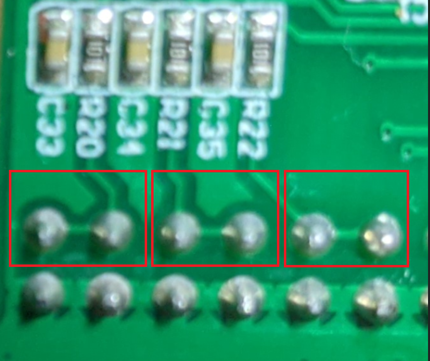
X = D9 = PB1 = pin 13 via R20
Y = D10 = PB2 = pin 14 via R21
Z = D12 = PB4 = pin 16 via R22

My first test drive was rather disappointing. After all that design work for the limit switch mounts, when using the stand-alone controller, nothing happened when running the sample G-Code and the limit switches were manually pressed. I would have hoped the woodpecker board would be interrupt-driven to detect the switch closures regardless of how the g-code arrived. There's a GitHub discussion where rseijo claimed "Zen, Yen & Xen had no connection points to the Atmega328" (confirmed to not be the case for me) and posted this useful header diagram:


As it turns out, the switches are not enabled by default! Thanks Anyzy for this useful tidbit:


Reading the fine print in the text block, we see that hard limits are enabled with $21=1 (of course they are). My $21 was found to be set to zero. Manually setting this to a value of 1 and tada! Upon pressing the limit switch while even manually moving the axis with the external controller, and the motion immediately stopped! See also the grbl documentation wiki.

Of course, there's probably a reason for having the feature disabled by default. Once triggered, all bets are off and the machine can only continue by pressing reset. Any work in progress is lost. Thus if any sort of stray noise or interference triggers the signal, well - that would certainly fall into the "undesired features" category; for example:
The machine stop working randomly with the spindle still running
And sure enough, if you see the settings posted, the $21 is already set on! So stray noise triggering these limit switches is definitely undesired.

I sure wish I had first found the Hackaday article that referred to an informative blog by Shahada Abubakar. One of the things I learned there: the reset switch is only one option to restart after a limit switch has been triggered. The other option:
 "This can be done by sending Control-X followed by $X"
There are additional tips on GRBL setting there, too.


Resources, Inspiration, Credits, and Other Links:


The road to CNC3018 Limit Switches

Almost two years to the day! It was way back in 2018 that I bought my first (and still only) CNC machine to learn more about G-Code and CNC in general. I bought one of the Twowin Tool CNC 3018 Pro machines from on AliExpress. The kit arrived in good shape, having been well packed. Assembly was quite fun and fairly straightforward. In the end I was frustrated that there was no good mounting solution for the limit switches. 


The folks over at LinkSprite have a pretty informative Wiki for desktop CNC.

One of my first CNC projects was this op-amp circuit etched into a bar of soap. (turns out soap is pretty forgiving, and a great way to learn to use a CNC machine). After a couple of sample runs, and my limited free time, it ended up mostly sitting idle in a box. So many cool projects, so little time.


It was about a year later during the summer of 2019 that I ordered the original Prusa i3 mk3s kit. This, too was quite a fun assembly project - although considerably more challenging than the CNC machine. I spent pretty much an entire weekend putting this together. It was really quite rewarding. The assembly instructions are very clear. The process is however quite time consuming. Plus, now I have a new appreciation for gummy bears. 

After assembly and a download or two from ThingVerse, my interest (and free time) waned somewhat. I had poked around a bit with various CAD programs, but nothing really sparked my interest. in printing designs from someone else. The printer then sat idle, too.

So here we are in 2020. I have SO MUCH more free time. Although I put in more hours for the Day Job from home, we don't travel or do much else these days. This leaves plenty of time to explore all these things I've wanted to learn!

It was a couple of months ago that I bought my next item on my list of "always wanted to have, but not sure what I will actually do with it": A reflow oven! I had a lot of fun retrofitting this as described in my prior blog. (it's no fun just to buy something, right?) 


Oddly, this was also the project to bring everything together. I thought it would be cool to etch my own Mylar solder stencil to try out my first SMD PCB: a reason to use the CNC machine! Oh, but the CNC machine needs those limit switches. I can print my own limit switch hardware! Oh, but I had pretty limited experience with mechanical CAD design. I need to learn Fusion360. Good thing that I have plenty of free time at home; chasing another bunny...

Printed books are great for reference, but not the best way to learn something hands-on like CAD software. Yes, there are a lot of YouTube videos, but most seem to be people showing off what can be done, instead of actually teaching the complete newbie, like me. Solution? This Designing for 3D Printing with Fusion 360 on Udemy This is absolutely an awesome class that got me kickstarted in Fusion 360. If you have little or no skills with Fusion 360, I highly recommend this class. Vladimir Mariano is clear, concise, articulate, and a real joy to learn from in this class.

Being able to design parts and print them at home turns out to be quite addicting, particularly if you happen to be a borderline perfectionist. There's somewhat of a chronology in my learning and skills here:


There's apparently a Grbl plug-in for OctoPrint; I'll need to take that for a test drive.

Enough of the background... on to the mounting hardware design...


Resources, Inspiration, Credits, and Other Links:

Find gojimmypi at gojimmypi.github.io

I'm currently working on my new blog home at  gojimmypi.github.io After implementing a variety of features such as dark mode , syntax hi...