Sunday, December 30, 2018

Favorite Gizmos of 2018

As the end of 2018 approaches, I thought it might be nice to share a list of some of my favorite electronic gizmos. In no particular order:

It's difficult to have any gizmo list without the Raspberry Pi being listed. So voila, let's move on.

One of my favorite gizmos is the DPS5015. In and of itself, perhaps not super interesting: your basic Programmable Supply Power Module. However it was the first commercial product that I "re-purposed" and learned a lot of hardware hacking as noted in my blog from 2017.


I think some of the most amazing devices are the SDR gizmos, such as the NooElec NESDR Smart Bundle on Amazon. (On my wish list is the Lime Micro SDR). Last year I wrote a blog on streaming SDR information directly to an OpenWRT router. I also used my SDR during development of my LoRa button-pushing project (see below).

Also cool, although also not new for 2018 - is the M5Stack series of ESP32 modules, complete with enclosure and display.

I wrote a blog about the M5Stack LoRa range, as well as a blog about my LoRa-GPIO project (pushing a button from afar). A prototype M5Stack that had both an AVR and ESP32 device turned out to be quite the educational experience as noted in my Serial Port Debugging blog, featuring the Rigol Oscilloscope Protocol Decoder. (see also Dave's EEVBlog Review of the DS1054z)

Early in the year, I bought an inexpensive Altera Cyclone IV EP4CE6 FPGA Development Kit and wrote a blog about it. This was my first experience with FPGA and proprietary tools (Quartus).

Cyclone IV FPGA Dev Board
I think one of the most significant new gizmos of the year was Luke's tinyFGPA BX. Be sure to follow @tinyFPGA on twitter. Learning to program an FPGA is something that I've been wanting to do for a long time. Luke - along with a bunch of other FOSS advocates, such as FPGAwars - have finally made it easy and inexpensive for the newbie. There's some really great BX getting started information. One of the coolest FPGA programmers has got to be Icestudio.

Late in the year, [@esden] introduced another cool FPGA device on Crowd Supply called iCEBreaker. Some folks lucky enough to attend conferences have been able to obtain theirs... others (including me) will not have them until delivered until next summer.

Finally - at the very end of the year, there's also the Fomu Crowd Supply project - An FPGA board that fits inside your USB port! (also due next year)

There's an excellent web-based Verilog editor and simulator online from the folks at 8-bit workshop. Be sure to check out their new book Designing Video Game Hardware in Verilog, as well.

Once I get a handle on FPGA programming, I plan to do something with this AD/DA board I found on ebay. (using AD9280 & AD9708)

At the very end of the year, I found the XGecu TL866II Plus USB Programmer from the XG Autoelectric folks (see also xgecu.com), thanks to @tinycompblabla.  At only about 50 bucks, it is considerably less expensive than something like the elnec or dataman. I'm looking forward to receiving it in January.

On the topic of component testers, is the AVR-based M328 Transistor Tester project. (source code here). This is really a quite clever device that automatically detects what component is connected, then indicates whether it is good or not. For things such as transistors, basic key characteristics such as gain and Vbe are displayed.


M328 Transistor / Component Tester

See also the ISP pins in case you want to get creative with your transistor tester.

One of the cool gizmos that I recently purchased is the Arduino MKR WiFi 1010 (also available from Amazon). Atmel SAMD21, ESP32 WiFi, ECC508 Crypto-Authentication, all in one place! This gizmo is so cool, I wrote an entire blog about SWD programming the Arduino MKR WiFi 1010 with the Atmel ICE.
Atmel ICE and MKR WiFi 1010
In the Fall of 2018, I found this cool SPIdriver dev board on Crowd Supply. This too, was so cool that I wrote an SPIdriver blog about it. Note that the same guy has an upcoming and similar I2C driver project, as well - that looks just as cool.

Although perhaps not a gizmo in the pure electronic sense... I did buy myself an inexpensive 3018 Pro CNC machine - as CNC programming is also something I've always wanted to learn. I need to get my thoughts together and put all that information in a blog entry soon. Stay tuned.

This blog is still a work in progress... if you think of any gizmos that I should look at and perhaps add to this list, let me know via twitter or @ gmail.

Wishing everyone health and prosperity in the coming new year.

Cheers.


Sunday, December 9, 2018

SWD Debugging the Arduino MKR-WiFi-1010 with Atmel ICE

Over the weekend I received my new Arduino MKR-WiFi-1010 (the ABX00023) that I purchased from Amazon, as seen here along with my Atmel ICE:


Warning: after writing this blog I realized that using the Atmel ICE can end up causing problems with the bootloader when later attempting to upload a sketch via the serial port! This was easily resolved (everything is easy, when you know how), but beware.

Update: I wrote this blog on Burning Bootloader from Visual Studio with Atmel Ice for the Arduino MKR WiFI 1010.

Ironically, I found this board shortly after commenting to Peter Scargil that I really didn't think anything could replace the Espressif ESP8266 (other than the ESP32) since it has been around for so long and has such a strong community and momentum. I found the 1010 shortly after seeing a tweet from MicroChip regarding the ATMega4809. (an 8-bit Arduino, 16MHz ceramic resonator, WiFi board using the ECC608 Crypto-Authentication chip for $44.90). The MKR1010 (32 bit!) was listed as "related product".  Now, I knew the MKR-1010 board had been released some time ago - but at the time I seem to think it was rather expensive and didn't think much more about it. However at $29.90 - that's just too appealing to pass up. Amazon prime to the rescue for me gizmo addiction: delivered the next day at no extra change! Thank you Prime!

It has been some time since my last blog post. I have a draft blog of some things that I learned with my new CNC, but it is rather messy at the moment, so instead this weekend I am back to debuggers and this MKR-1010 board.

One of the main points of interest with this board - is that in addition to the SAMD21 (specifically the ATSAMD21G18A) it also has an on-board ESP32 ... and the MicroChip ECC508 Crypto-Authentication chip! Although I really like the ESP8266 boards, I will say that JTAG debugging was not exactly the easiest and most robust, as noted here and here. One thing about the Atmel ICE is that in Atmel Studio, it is a fairly robust and reliable hardware debugger.

So fresh out of the gate, I was disappointed that I did not have a cable for (what I thought) was the Single Wire Debug (aka SWD) connector:

Comparing a 50 mil connector to what I thought was the SWD connector.

Note that black connector not a 0.1 pin spacing, it is already the small 50 mil connector that is on the Atmel ICE. The white connector below is even smaller than that!

I spent an embarrassingly long time scouring the internet for anything I could find on "Arduino MKR 1010 SWD Debugging Connector". I could not even determine what that tiny white connector is called so that I could order one. I even posted a plea for help on the Arduino MKRWiFi1010 forum,

Eventually, I found this post where someone was asking about connecting the Atmel ICE SWD to the MKR-ZERO. Although I had no indication the 6 pads on the underside of my MKR-1010 were actually the J2 SWD pins, I was hopeful that the folks at Arduino would have standards and consistency.

Schematic diagram for MKR-1010 SWD Connector (pads on reverse)

The Maker Zero SWD pins are as shown here, in this diagram provided by Federico_Vanzati:

MKR-Zero SWD Pins for Atmel ICE
Keep in mind I had no experience, no knowledge of the MKR-Zero, however the MKR WiFi 101 is just a bit similar, once you see them both, eh?
MKR-1010 board from the Arduino site
So although I was confident and hopeful that I could finally get the Atmel ICE to connect, I was still stuck with 6 pads and no holes. I really wish the Arduino folks would have made a more debug-friendly connector.

Fortunately, I had some of those snap-apart headers on hand. I bent two sets of 3 pins...


Header with some pins bent for the surface-mount SWD pads.

...and stuck them both into a 6-pin cable connector to hold them in the proper position for soldering:

Preparing the home-made surface mount headers in a 6 pin connector.

Be sure that the longer header pin is not pulled through when bending them: Not only do you want to have a good length for electrical contact, but you also don't want them too long on the PCB. Yes, there's a solder mask layer that should act as an insulator, but I would not count on it.  Make sure that pins are only as long as the solder pads. I needed to trim mine.

Note that using sets of three will increase overall mechanical strength - but as they are surface mounted, care should be taken when inserting & removing connections.

So the reality of annoying future breadboard use becomes quite apparent once the header is soldered in place. Clearly the designer prioritized the Arduino logo over the practicality of pad header placement:

My MKR-WiFi-1010 SWD Header Connection, freshly soldered on

I'm thinking if I plug it into a breadboard, I'll just use some of those stackable headers. Still, this will leave many more mechanical connections and many more places for connection problems.

From the MicroChip / Atmel ICE docs - these are the pins used for SWD on the SAMD21 chips:

SAMD Pins for SWD Debugging with Atmel ICE (from the User Guide)
Upon reading the pinouts and looking at the cables and adapters that I have for the Atmel ICE, I realized that my only option was to use that handy-but-annoying Squid Cable.

Arduino MKR WiFi 1010 with SWD Atmel ICE Pin Numbers shown.

Here's what the board looks like connected to the Atmel ICE:

Arduino MKR-WiFi 1010 connected to Atmel ICE with the Squid Cable.

I sure wish a simple 10-pin header would have been installed on the MKR boards - that would connect directly to the Atmel ICE debugger. Well, no worries.. good to go!

There's a MKR-Wifi-1010 tutorial on actually using the WiFi here on GitHub. I actually used the WiFi tutorial page to get started. I took the ino file and pasted it into the Arduino IDE and compiled to ensure everything was working properly. Then I created a new Atmel Studio project from the ino.
Atmel Studio setup step 1.

And on the next screen, select the location of the ino project from the Arduino IDE:

Atmel Studio setup step 2.

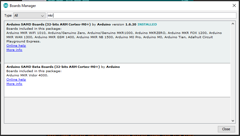
Edit Feb 2019: If you don't see the board listed, then launch the Arduino IDE and ensure it is installed via Tools - Board - Board Manager:


Type "MKR" to shorten the list:


/Edit... back  to Atmel Studio:

Connection in Atmel Studio is pretty straightforward, just select the Atmel ICE and ensure "SWD" is used:

Atmel Studio SWD Debugger Settings for Atmel ICE
After that... voila! Click the Debug menu and step in, set breakpoints, and more!


One thing that is not super obvious when debugging with the Atmel ICE, is most sample code is "wait forever until serial port available" during setup. Well, the Atmel ICE is not the serial port!


  //Initialize serial and wait for port to open:
  Serial.begin(9600);
  while (!Serial) {
    ; // wait for serial port to connect. Needed for native USB port only
  }


So be sure to connect something to the serial port! The serial monitor in Atmel Studio is a bit wonky. I simply use putty.

See the Disassembly tab to view the assembly language generated from the source code:


The Processor button show interesting information:


Also cool to browse and inspect I/O registers:


This is SO much better than a zillion serial.println statements!

Well, I hope this saves you the hassle I encountered when trying to use the Atmel ICE hardware debugger with the Arduino MKR-WiFi 1010.

I've added a MKR-WiFi-1010 GitHub Repository with the source code and relevant pictures and documentation.

So ya, perhaps this Arduino will take over the Espressif chips ... but as there's an Espressif on-board this guy, perhaps that's not a fair comparison. Still - it is a quite interesting board at a somewhat reasonable price.

Resources, Inspiration, Credits, and Other Links:


Please leave comments, ideas, suggestions below (moderated, sometimes delayed) or send me a message at gmail, or find me on twitter.

Sunday, September 2, 2018

SPIdriver

I recently backed an interesting SPIdriver project on Crowd Supply. For as little as $27 you can have your very own SPI debugging tool!


First, it should be noted what this device is, and what it is not. As clearly stated by the name - it is a driver and not a monitor. There's an open issue on GitHub regarding monitoring, I'm interested in seeing what happens with that. But really, for monitoring, that would be the job of an oscilloscope - ideally a DSO, or even better: a logic analyzer.

There was a (slightly misleading) but otherwise interesting review by the folks over at linuxgizmos that mentions the word "monitor" several times when describing the SPIdriver.

Still, I had hoped to see how complex of an undertaking it might be to add the monitoring feature.  When I looked at the source for the firmware, I kinda just stared in bewilderment for a few moments: "What is this strange language?"- but then back in the README, I noticed in the first line: "It uses the MyForth compiler written by Charley Shattuck and Bob Nash". wow. Forth! And not just any Forth:
This version is intended for embedding in small 8051 based projects. They currently feel the product is not commercial worthy as it has too many personal enhancements, and is more an exploration of concepts than a real product.
Really - I'm impressed that not only someone could code something in this language, but as noted on the documentation page:
This version is intended for embedding in small 8051 based projects. 
So even more impressive is that this code is compiled and loaded into... (?) what specific chip: "Silicon Labs automotive-grade microcontroller"? I'm not really sure, but have requested the schematic be made available. The article mentioned above claims the controller is an EFM8 8051-based 8-bit MCU. The text on chip includes 8810 and 1743; not much luck when googling this. So I have not confirmed the exact processor being used. I've not coded for the 8051 in quite some time, and certainly never in Forth. It is good to know this chip is still around if that's what's here.

Not only do I have pretty much no Forth-programming skills; further, I have no idea how the binary, once compiled, would even get on the chip itself. Perhaps something like avrdude is used? I wonder if the code comes in via the serial port, or perhaps the bi-directional SPI port? (Hopefully not another vendor specific, proprietary IDE)

In any case, the code seems to work well for the intended purpose: The FTDI chip acts like a serial port talking the to SPIdriver controller. The device works some magic converting serial port text commands into SPI control signals - and displays them!

The initial out-of-box experience was quite good; I had the device working almost immediately thanks to the great documentation page. It would have been sooner, had my Ubuntu VM not been in the middle of an update. (thus preventing me from installing anything new). The Windows command-line does not work quite as documented, since the ports are not named /dev/ttyUSB[n]. Fortunately the parameters accept Windows-style port names:


>>> from spidriver import SPIDriver
>>> s = SPIDriver("com16")
>>> s.sel()
>>> s.write([0x9f])
>>> list(s.read(3))
[127, 255, 255]
>>> s.unsel()
>>> quit()

Very cool. Moving on from the initial test, I played a bit with the pre-compiled Windows executable. Minor stumble here, as my 64-bit Windows 10 installed the app into the x86 directory, thus the sample command-line was slightly different than the docs:


C:\workspace>"c:\Program Files\Excamera Labs\SPIDriver\spicl.exe" COM16 i
The system cannot find the path specified.

C:\workspace>"c:\Program Files (x86)\Excamera Labs\SPIDriver\spicl.exe" COM16 i
uptime 61  5.029 V  0 mA  29.0 C


The Windows GUI makes it ridiculously easy to send SPI commands. Up to two hex digits can be entered and sent with each "Transfer" button press:

SPIdriver Windows GUI

Resulting in the display on the SPIdriver to look like this:


SPIdriver sample SPI signal
Note that if you exit the SPIdriver Windows app, you may need to wait a few moments for the process to be completely killed; Otherwise when starting a new instance, I found that the data entry box would sometimes not accept any characters.

On to a more impressive and complex, sending an entire picture to another SPI display! Here too, I had a minor stumble, as the docs claim that  the command looks like this:


python -h /dev/ttyUSB0 st7735s.py grace.png


This brought up the python help for me, and ignored the rest of the parameters. On Windows the command was this one (also note different picture):


python st7735s.py -h COM16 spidriver.png


Resulting in this:

SPIdriver talking to an SPI display
Sadly, I could not find a convenient SPI memory device laying around (at least not one I was willing to possibly fry), so I could not continue with the sample SPI flash. But while digging through my parts, I found an ENC28J60 SPI Ethernet board like this one that I've been meaning to play with. Coming soon...

Other notes:


Please leave comments, ideas, suggestions below (moderated, sometimes delayed) or send me a message at gmail, or find me on twitter.


Sunday, July 15, 2018

Pushing a button. From afar. With LoRa.

This blog entry is about pushing a button. Seems simple enough, eh? Except when the button you want to press is very far from where you are physically located... say, when there's a remote gate control well out of sight and out of range for the remote. Oh, and it is also too far to have any network connectivity. What to do?

My plan is to use LoRa to communicate from an M5Stack console to a distant LoRa32u4, each equipped with a LoRa module; essentially push the button of the remote from afar! The actual pysical button push on the M5Stack will essentially be "sent" (via LoRa message) to the remote 32u4 which will then trigger the actual remote control transmitter. The working prototype is shown here:


How to get there: The first thing needed is to disassemble the remote and determine how it normally works. The remote I am using is a Somfy TR2 similar to this one that can control two different devices. Upon disassembly, the first thing we see is those two buttons each with 4 pins. The buttons appear to be very similar to this Grayhill Gull Wing 95C06C3RAT at Mouser as documented here. Note that although there are 4 pins, it is simply a SPST switch:

Photo credit: Grayhill spec sheet

I confirmed both visually and with an ohmmeter that indeed I have a similar switch and proceeded to connect some external wires to it:

Somfy remote switch wiring

If you look closely, I took the time to wrap the wire around the pin of the switch to make a good mechanical connections, while being careful not to touch any other circuit. It would probably be a good idea to use some hot melt glue and affix the wires to the pc board.

Here, Green is a ground (all 4 pins, 2 from each switch); Orange is BP1 and Yellow is BP2. The top of the battery is labeled as being the positive side. The entire metal surface here is at 3.3V:


This turned out to be an extremely handy arrangement for me: the entire device could essentially be the "load" for an NPN transistor circuit!

Putting an ammeter between either the orange or yellow pins to ground, I found about 0.3mA that would otherwise flow though the button (or a transistor).

Looking at the specs for the 2N3904, the max collector current is a whopping 200mA  max, well over a couple orders of magnitude for what we'll need:


And for a collector current of (we'll round up) to 0.5 mA, we'll have a minimum gain of around 60 to 80 (let's pick a gain of 70 for discussion-sake):


We'll need a base current of around  (0.005A / 70) =  0.0714 mA;  For the current-limiting base resistor, we'll thus need: 3.3v / (0.0000714) ~= 40K ohms. I didn't have a 40K handy, but I did have a bunch of 20K ohm resistors laying around, so I'll use that. It is still well within spec, and will certainly account for any gain drift or degradation.

Our button-pressing supplement thus looks like this (shown for BP1, but the same for BP2):
Note that this circuit will allow our 32u4 to control the remote via a GPIO pin. Fortunately the remote is also smart enough to turn itself off - if for some reason the button remains pressed so that the battery does not drain (such as being poked by your keys in your pocket). In our case: regardless of the state of the pin during power up (or application crash) the battery will be preserved.
The manual prototype looks like this:


Note the red wire to drive the base of the transistor is stuffed into the battery holder for the picture. Once in operation this red wire will instead be the GPIO output from the 32u4.

Next, we need to make sure the remote is actually working! As mentioned in my previous blogs on M5Stack LoRa Range Issues as well as this fun project using OpenWRT on EA3500 with RTL-SDR Stream, I have an inexpensive NooElec SDR, that is simply amazing - particularly given the price! With this hardware, and the some software, we'll be able to "see" the remote signal.

The last time I used Cubic SDR, it was working fine. Today? Nothing. Erg. Gotta love Windows. App starts, no complaints, but no signal. A little bit of googling, and there's the Quick Start Guide. First thing I noticed was mention of my old friend, zadig. Sure enough: during one of the the Windows updates, the default driver was changed for some bizarre reason. Here's the screen just before correcting it:


And tada! Exit Cubic SDR (no need, at least for me, to reboot computer)... relaunch Cubic SDR app... then pressing Start for my RTL2832U device:


The waterfall immediately starts! Press the button on the remote a few times, and we can see the pulse at about 433.5 MHz. Notice the messy side-band noise, as well as someone else continuously transmitting at about 432 MHz:


I have the source code for all this on GitHub here: https://github.com/gojimmypi/LoRa-GPIO (note there are also Development and M5-RadioHead branches, but after a bunch of GitHub fussing, I think the master branch is now up to date). The projects are VisualMicro extensions to Visual Studio, but I suspect the Arduino code would work just fine in the Arduino IDE.

More to come...

Saturday, June 30, 2018

AD9280 AD9708 AD / DA Module for AX series FPGA Development Board


I keep seeing these AD/DA modules on ebay, (such as this one) but I've not been able to find much  documentation. There's of course the Analog Devices AD9708 and AD9280 spec sheets, but not much else for the board itself.

"The AD9280 is a monolithic, single supply, 8-bit, 32 MSPS analog-to-digital converter with an on-chip sample-and-hold amplifier and voltage reference" ... "The AD9708 (digital-to-analog converter) can support update rates up to 125 MSPS"

When considering a board, the AD9764  14-bit also looks interesting, but it appears to be obsolete. There's a newer AD9246, but I could not find a site that listed the eval board for sale: (e.g. mouser, digikey, etc). In fact, there are a LOT of options: Here's a list of Analog Devices Eval Boards at Mouser. There's also this Precision ADC selector Guide. I'm pretty sure I'm just interested in the ones on page 5: Analog Devices’ single channel successive approximation register. There's kinda no limit to the options, such as this impressive AD9172 Dual, 16-Bit, 12.6 GSPS RF DAC with Channelizers  (spec sheet); yes that's over TWELVE BILLION, 16-bit samples per second. ZOOM!

So many choices... I ended up exhausted trying to find something with a high sampling rate, and a large bit width, and a low cost for simply experimenting. So in the end the 8 bit dual AD and DA on one board for about $20 bucks was hard to beat.

For this board, I've found two different pin numbering schemes: one that uses the traditional left-right, 1-2 number used in most ribbon cables, (so that the ribbon cable wires are sequentially numbered)... and I would think that this is the correct pin numbering:


However I also found this somewhat "DIP-style" numbering used on integrated circuits, running sequentially down one side, then the other (although the numbering is reversed on the second column). I'm hoping this is not the correct wiring, but I will not know for sure until my board arrives.:


See video clip here.

They seem to be in agreement with pin number (e.g. Pin 5 is DA CLK)... but the point is: where exactly is that pin on the header?

I did eventually find this interesting article from Hackaday regarding using this board to build a software defined radio for the Raspberry Pi using the Icoboard plug-in with a Lattice iCE FPGA  (this may tie in well with my recent iCE40UP5K-B-EVN purchase!) The the icoboard is for sale here, for about 80 euro. Note for that price you also get 8 mbit of RAM on the back of the board!

Info starting here in the video.


Sunday, May 6, 2018

Programming the Lattice Semiconductor FPGA iCE40 Ultra Plus Breakout Board iCE40UP5K-B-EVN

FPGA programming the Lattice Semiconductor iCE40 Ultra Plus Breakout Board.

(work in progress, come back soon)

TL;DR
Lattice Semiconductor tweeted a "new low price" for their iCE40UP5k-SG48 breakout that I simply could not resist. I've been wanting to learn FPGA programming for some time, and had recently taken the Altera Cyclone IV for a test drive. I was not super impressed with the Quartus software, so I was interested in seeing how well the Lattice Diamond software worked in comparison.

Lattice iCE40UP board diagram from the User Guide


I initially tried to order the board from DigiKey. I gave up fussing with their dreadful ordering UI/UX and instead I ordered it from Mouser. (specifically this iCE40UP5K-B-EVN item on the Mouser web site). The device arrived about a week later.

There was a (clearly hand-cut) quarter sheet of paper with instructions included with the board:


Mainly of interest are the links:

  http://www.latticesemi.com/ice40ultraplusbreakout

      and

  http://www.latticesemi.com/software

.. and the reminder to put the jumpers on J6 in the "vertical position" (perpendicular to the jumper at J7)

Despite the seemingly simply instructions, my initial out of the box experience was dreadful. Not only was the computer completely unable to connect to the board for the demo, but later once I was able to connect without the error, the demo didn't even work. I don't think my board shipped with the demo program installed, nor was I able to find the source code anywhere to try it.

The first problem seems to have been the fact that I already had installed FTDI drivers for my ESP32 development some time ago (specifically the rather rare JESP32). This was apparent when *both* FTDI devices were listed at the bottom of device manager, and when looking at properties - both were configured as JTAG devices:


Looking back, I suppose this makes sense, as the JESP32 that was previously installed has the normal order of the devices reversed:
"Yeah. I used FT2232H interface 0 for UART and interface 1 for JTAG. This is different from many other debuggers. Advantages being you get same /dev/ttyUSB0 UART like many other dev boards. Also (which I heard) you don’t need to modify kext under OSX" - @ba0sh1
Sadly when the Lattice iCEcube2 software installs, it does not configure the ports properly. I ended up manually removing the drivers, then manually installing them. I'm pretty sure when I revisit my JESP32, it will not work.

I was unable to find any useful sample code for the iCE40UP5K. I eventually found this:

https://github.com/cliffordwolf/icestorm/tree/master/examples/up5k_rgb

I was unable to program from the Lattice iCEcube2 software, as there was no "Tool - Program" on my menu!


I needed to download the "Standalone Diamond Programmer" from here:

http://www.latticesemi.com/Products/DesignSoftwareAndIP/ProgrammingAndConfigurationSw/Programmer

Don't bother using the site search to find this! Seemingly every software item *except* the one you want will be listed in the hundreds of results. (yes, I mistakenly tried installing an older version, and the iCE40UP is not listed as a device). The version that worked for me was 3.10.0.111.2 (I manually installed this one, different than the one that came with Lattice Diamond install) Specifically this link:

Programmer Standalone 3.10 64-bit for Windows

From the iCECube2 output, once a project is successfully compiled, the resulting file can be found in the log output near the end (see above). In my case, the bin file was found here:

C:/lscc/iCEcube2.2017.08/sbt_backend/Projects/blink/blink_Implmnt\sbt\outputs\bitmap

Note the annoying, sloppy use of forward and back slashes. They will need to be edited in Windows, otherwise an error occurs when pasting in the path.


Windows only likes back-slashes, so each will need to be individually changed. In my case, the default project ended up in:

C:\lscc\iCEcube2.2017.08\sbt_backend\Projects\blink\blink_Implmnt\sbt\outputs\bitmap

And the file needed (mysteriously) is prefixed with "top_". Select that bin file in the Diamond Programmer by clicking on the little 3 dot ellipsis button:


It should pop up a dialog box like this:


Note the device family is set to iCE40 Ultra Plus and the Device is iCE40UP5K.

Double-click on the "Operation" column (or click the "Device Properties" button) and ensure these settings are in place:


I saved my working project to GitHub here: https://github.com/gojimmypi/iCE40UP5k-blink

Once working, when viewing with Zadig, this is what I see (note Interface 0 and Interface 1):


However programming is not always successful, even if the software finds the device:

INFO - Check XCF Project: The current XCF Project is valid.
INFO - Check configuration setup: Start.

INFO - Check configuration setup: Successful (Ignored JTAG Connection Checking).

INFO - Device1 iCE40UP5K: Fast Program


 "Device detection failed. Cannot continue."

ERROR - Process Operation Failed.

INFO - Elapsed time: 00 min : 00 sec

ERROR - Operation: unsuccessful.

ERROR - Programming failed.

If the programming fails like this, try switching ports. One one computer (one that I had not installed JESP32 FTDI drivers)... I was able to program on the default "Port 0" (FTUSB-0) - on another computer (the one I previously had configured FTDI drivers, I had to change to "Port 1" (FTUSB-1) in order to program.


In the end I was eventually successful, but I don't think the iCE40UP5K is for everyone.


Find gojimmypi at gojimmypi.github.io

I'm currently working on my new blog home at  gojimmypi.github.io After implementing a variety of features such as dark mode , syntax hi...