Friday, March 31, 2017

STM32 Smart V2 to ST7735 TFT LCD Interface

Here are my notes on interfacing your basic 1.8" ST7735 TFT LCD display with an STM32 Smart V2 board such as this 1-8-inch-TFT-LCD-ST7735S-Display-Module128x160-51-AVR-STM32-ARM-8-16-bit listing on ebay.


This should have been a trivial project. The STM32 board has an 8 pin female header. The display board has an 8 pin male header. As with most things, getting it to actually function was way more difficult than it needed to be. Upon inspection, the pins are not a match. Fortunately the Vcc and GND are - so at least it is unlikely the board would be fried when plugging in, but it certainly won't work. More specifically, here are the pins:


To make matters worse, even the sample code I planned to use was using yet another set of pin definitions (Port B, pins 3 to 7 including soft reset):


So ok, first whip together a bunch of jumper wires to make sure everything actually works. 

The octopus of jumper wires is really not very appealing. So I spent some time making a little adapter. (for the time it took, I'm glad I am not planning a production run!)

Here's the interface modifications needed:


And here's what my newly created adapter looks like:


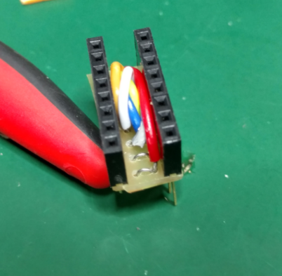
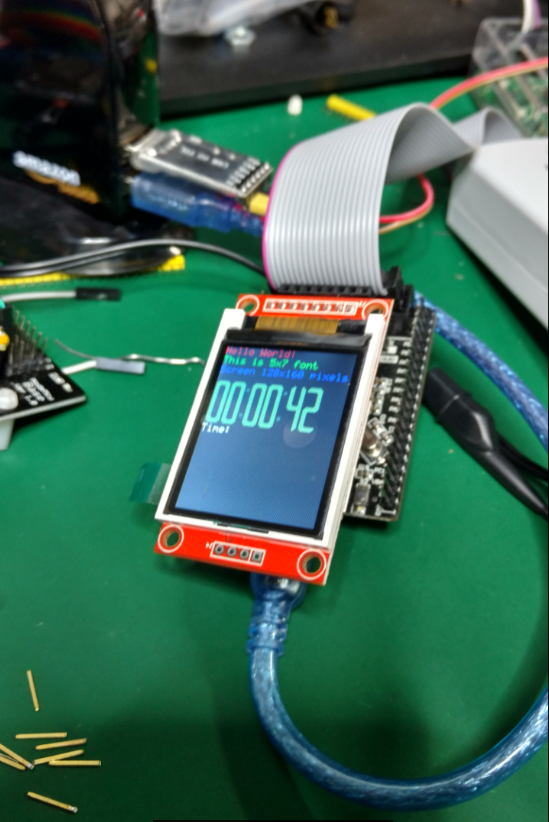
This allows a somewhat more graceful connection, sans poulpe:


One the software side, things were just as annoying - but of course way easier to fix. (no dremel tool to cut proto-board, no wiring, no soldering!)

I found this really excellent STM32 ST7735 library on github:


The code was of course not plug & play... but it was very close. In addition to the pin definition inconsistencies - I also had the problem of IDE. Apparently the code on github was created with something that knows how to deal with a "coproj" project file (I have no idea what IDE is needed).

So I cracked open my old time friend Visual Studio with the VisualGDB add-in. I first created a project with the STM32 HAL, then quickly realized the sample code was not implemented with HAL... so I tried again, creating another project this time with the STM32F1 Legacy Peripheral Library.

Type STM32F103C8 in the filter to find the MCU chip used in the board.


Then pick the "LEDBlink (StdPeriph)" sample project to generate:


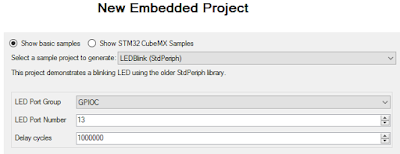
Note the LED setting for the STM32 Smart V2 is on Port C Pin 13.

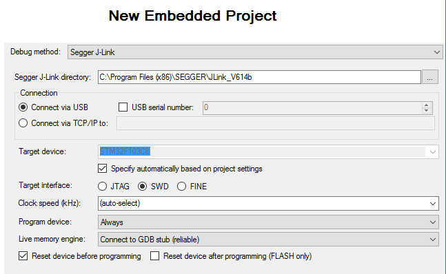
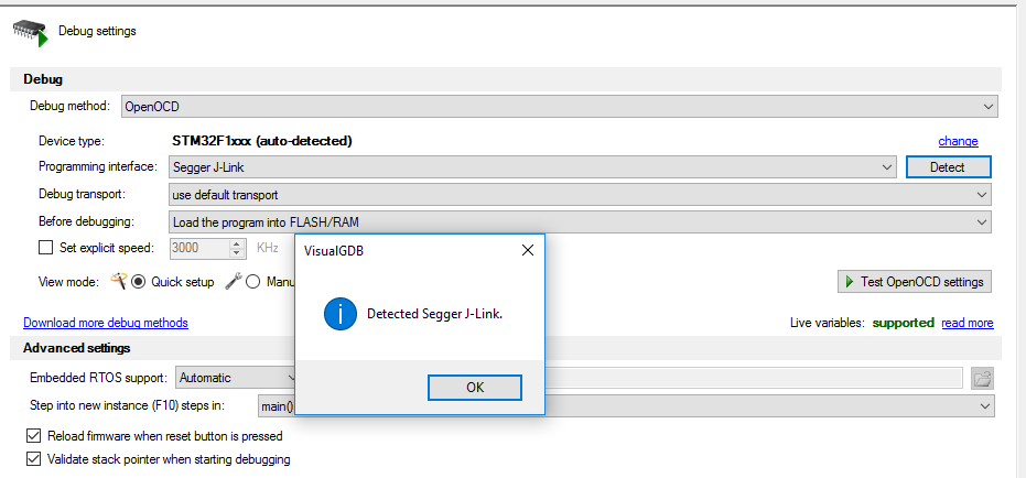
On the last page, pick your debugger. I'm using a Segger J-Link:


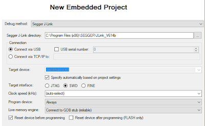
(I have some other Segger USB tips here)

In order to add ST7735 LED Display support, only the main project directory files need to be copied from the github sample (VisualGDB has its own support files in the path). In this case: main, delay, font5x7, garmin-digits, and of course STM7735 files:


The crmsis and stm_lib directories can be ignored.

Note that since the project created the LEDBlink.cpp file, that file will need to be deleted, as it also has a "void main()". Consider copying the LED blink code if interested.
 
There were a variety of "issues" that needed to be addressed. For one, although the files ending in ".c" were included in the project, for some reason Visual Studio could not seem to "find" the code, giving me a ton of "undefined reference" errors. There are a bunch of other files that end in ".c" so I really don't know why the problem... but in renaming them to ".cpp" seems to have appeased the compiler.  (there's likely a setting someplace that distinguishes a "C" app from a "C++" one.

Things went a bit rough at first. Even once I was able to get the app to compile, I ended up stuck in some interesting code:


I had a difficult time with the suggested DEBUG_DEFAULT_INTERRUPT_HANDLERS. Fortunately the kind support folks at sysprogs forum had some helpful advice:


And sure enough, when turning on the DEBUG_DEFAULT_INTERRUPT_HANDLERS feature in Visual Studio Project Properties: C/C++ Preprocessor Definitions:


The problem was immediately obvious. The SysTick_Handler was not properly configured (despite being right there in delay.c; renamed to delay.cpp). The problem here seems to be the difference between the original C code, and this C++ project. It needed to be prefixed with extern "C":


(a compile-time warning might have been nice here)

Once everything compiles successfully, a few more changes are needed to point the controlling pins at the ones actually used on the STM32 Smart V2 board. This is all defined in the SM7735.h file:

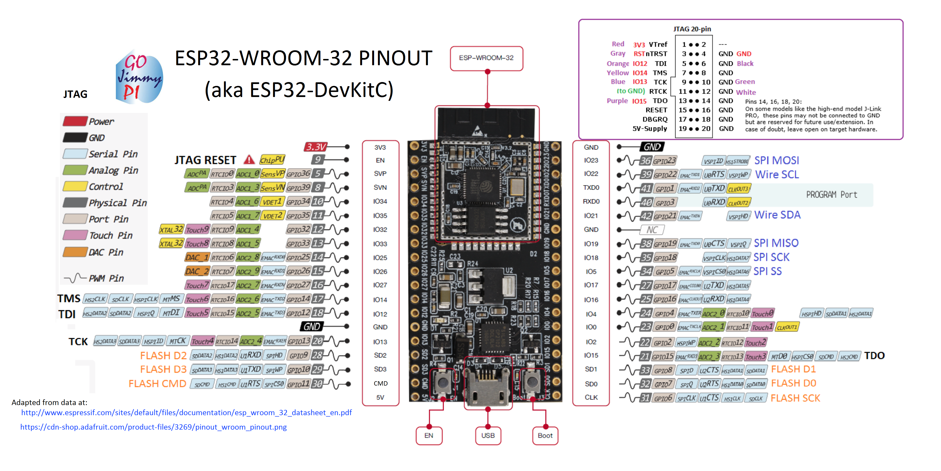
This board uses GPIO Pins 13 and 15 (SPI Port 2), so set this in the config file:

#define _SPI_PORT 2


Additionally, the A0 and CS pins need to be set. From the pin diagram, A0 is Port B pin 1, and CD is Port B pin 12. 

#define ST7735_A0_PIN GPIO_Pin_1 
#define ST7735_RST_PORT GPIOB
#define ST7735_RST_PIN GPIO_Pin_6 
#define ST7735_CS_PORT GPIOB
#define ST7735_CS_PIN GPIO_Pin_12 


Reset is hard wired to actual reset (NRST) line, so the "soft" reset functions will not work (e.g. RST_L and  RST_H).  In code, it is left assigned here to Port B Pin 6. The manual reset of the display occurs in void ST7735_Init(void).  If you really want the soft reset, perhaps consider not connecting the NRST pin and instead wiring something up to the unused Pin 8 on the STM32 Smart board.

I've posted my source code here: https://github.com/gojimmypi/STM32-ST7735

If you are interested in the ST7735 display for the STM32, you may also be interested in some of the many other STM32 libraries created by LonelyWolf:

https://github.com/LonelyWolf/stm32


Monday, March 20, 2017

More on Segger J-Link and VisualGDB.

In my previous post, I explained the problem of J-Link JTAG drivers being changed by OpenOCD in VisualGDB, and my difficulty in putting back the proper drivers for use by Segger utilities.

Since posting this information to twitter and sysprogs forums, I've learned some interesting (and cool) things:

1) The clever folks at Sysprogs have their own "zadig-like" USB driver tool (strategically called USBDriverTool), that unlike zadig, has a "put back the original drivers" feature:


And can be downloaded (free!) here:

http://visualgdb.com/UsbDriverTool/

2) Additionally - the kind support folks at Segger responded to my email and pointed out that VisualGDB also supports talking to the Segger GDB server directly (instead of using OpenOCD). There's even an excellent example:

https://visualgdb.com/tutorials/arm/stm32/

Note in particular that instead of picking the J-Link device from the OpenOCD Debug method drop-down list, that there's a "J-Link JTAG" debug method also listed!


3) The Segger folks also have an explanation on the J-Link showing up as a BULK device in Windows. This is not a problem I had, but I am including this as relevant:

https://wiki.segger.com/J-Link_shown_as_generic_BULK_device_in_Windows

The screen snips there appear to be from an earlier version of Windows. Additionally, as noted in my proir post - simply selecting "Update Driver" would result in Windows saying that the drivers are already the current ones (even though it does not work). So you may need to delete the drivers before attempting the update when seeing this "BULK" driver issue.


Sunday, March 19, 2017

Fixing J-Link "No emulators connected via USB": How to have J-Link work for both Segger Utilities and VisualGDB (although probably not concurrently)

I recently discovered that none of my Segger J-Link utilities worked any more.

My fix for: "No emulators connected via USB":

The solution took me hours to figure out. Hopefully this post will help others with a similar problem.

Specifications:
  • Windows 10 Version 1607
  • J-Link EDU Version 10.1 (16-45) Part No 8.08.90
  • SEGGER J-Link Commander V6.14b (Compiled Mar  9 2017 08:46:23)
  •   Firmware: J-Link V10 compiled Jan  9 2017 17:48:51
  •   Hardware version: V10.10
  • Visual Studio 2017
  • Visual GDB 5.2.14.1389
  • STM32 Smart  V2.0 (STMF103C8T6) target board

I found that using VisualGDB to connect to my STM32 for some single-step debugging with OpenOCD was the cause.

The J-Link is properly detected, even with the wrong USB drivers in VisualGDB:


Upon testing OpenOCD connection in Visual Studio w/VisualGDB, this message will pop up, wanting to change the USB drivers:


Not changing the drivers... well, no debugging will be available in Visual Studio. Changing the drivers will make OpenOCD happy in VisualGDB:


But I had setup VisualGDB weeks, perhaps months ago. And that change only occurs once.

These alternate drivers used by OpenOCD in VisualGDB are apparently not at all compatible with the Segger J-Link utilities. Trying to run jlink.exe results in the completely useless error message "No emulators connected via USB":


Unfortunately, a simple re-install of the Segger Software, Utilities and USB driver does not solve the problem. Even the uninstall of Segger software and USB drivers, reboot, run CCleaner, reboot, re-install, reboot does not help.

Oddly, when re-installing the Segger software...


(be sure USB driver is checked, it was checked s default for me)

...my J-Link shows up as a COM port that does not work with either J-Link utilities nor VisualGDB:


Manually installing a specific USB driver gives a "Driver not signed" error.


Besides, I have no clue which should be installed anyhow (64 bit or 32 bit or JLinkCDC.inf or JLink.inf)....

So you'll need to first uninstall AND DELETE the existing drivers:


If you don't delete the old drivers Windows will tell you the proper drivers are already installed (despite the fact that the J-Link does not work at all with Segger utilities nor VisualGDB when configured as a COM port).


Next, unplug (if still plugged in) and re-plug the J-Link back into a USB port. If your computer *still* does not recognize the device properly (read: if Segger utilities still think it is not connected), go to Device Manager, right click on the J-Link COM port, and select "Browse my computer" to the install location of the INF files:


And use the path of your Segger install. In my case this is:

C:\PROGRAM FILES (X86)\SEGGER\JLINK_V614B\USBDRIVER\

That should get your Segger utilities working again. Alas the J-Link won't work with VisualGDB anymore... and if you change the USB drivers to make it work, well... start the process all over again. :)


Some additional information:

There's an awesome tool out there called zadig that sees the J-Link like this when it works with the Segger utilities:


Note the "jlink" driver.

Here's what zadig shows when the J-Link is working with VisualGDB:


Note the change from "jlink" to "WINUSB".


Too bad that the list of drivers available in zadig does not include this jlink driver. Once it is changed, I have no idea how to put it back with zadig.

Really the solution should be on the Segger side - the same way that VisualGDB says "hey, I see your device but the wrong USB driver is being used, would you like to change it?". Or even better: simply work with the standard WINUSB driver.

My hope is that the folks at Segger and Sysprogs (the makers of VisualGDB) will cooperate and make switching between environments a little less painful. :)

In any case - this was my solution to  "No emulators connected via USB" for the J-Link JTAG debugger.

Note that I have more information on this topic in my next post here:

http://gojimmypi.blogspot.com/2017/03/more-on-segger-j-link-and-visualgdb.html

Saturday, March 18, 2017

Gizmo Compatibility


I'll be keeping track of my gizmo compatibility here.

See also: https://github.com/gojimmypi/Gizmos

  Atmel ICE Bus Blaster Bus Pirate Olimex
ARM-USB-OCD-H
Segger
J-Link EDU
ST
ST-Link V2
USB-ASP 2.0 (red)
Arduino Uno - - - (no jtag) (no jtag) (no jtag) -
Arduino Due - - - (no jtag) (no jtag) (no jtag)  -
"Blue Pill"
STM32F103C8T6
             
ESP32 - - - - - no -
ESP8266 - - - - - - -
STM32 Smart V2
STM32F103
- - - - - yes -
Wemos ESP8266 - - - - - - -

Friday, March 17, 2017

JTAG Debugging for ESP32

Notes and information on JTAG Debugging the ESP32 WROOM-32 (aka DevKitC, aka ESP32_Core_Board_V2)

I started off my day thinking I'd take my ESP32 for a JTAG test drive. Searching for pinouts I quickly realized there are known bad pinouts floating around. This was quite a surprise as the ESP32 has been out for well over a year. I wasted a ton of time on that. I'm posting my findings here.

As one might expect - the Adafruit pinout appears to be the most accurate one:


WROOM-32 ESP32 Pinout
 from: https://cdn-shop.adafruit.com/product-files/3269/pinout_wroom_pinout.png

(many thanks to the folks at @esp32net for responding to my tweet and helping to identify correct pinout).

So if you happen to see the pinout on the sparkfun site, the information is WRONG (hopefully they will correct it soon):

https://www.sparkfun.com/news/2017 (bad pinout here!)

I modified a known-good pinout image to create this little reference to easily identity a bad ESP32 pinout. Hint: look for the locations of the GND pins.


Not all online pinouts are accurate. Here's where to find proper GND on ESP32


Really, the ultimate authority is of course the Espressif data sheet:


The PDF has this pinout overview, with the functions listed in a table on the following pages of the PDF:


See also the Espressif ESP-IDF docs on GitHub:

Ok, so once the correct pinout is found - there was a moment of "oh no, all the JTAG pins are not available on my CoreBoard V2 breakout (grumble, grumble I don't want to solder them on)". But no... all good. Who would think that SD2 = TCK?

I should mention that "ESP32_Core_Board_V2" is the same as "ESP32-DevKitC"

Resources available here:

In particular the PDF of schematic found in "ESP32 Development Board Reference Design":

found in the zip buried in this directory:
ESP32_Development_Board_Reference_Design\ESP32-DevKitC(ESP32_Core_Board_V2)\01_Schematic


I took a variety of sources and copy/pasted into a new pinout diagram for myself:


This one is the whole dev board and includes the 20 pin JTAG header, and my (arbitrary) color code:

ESP32-WROOM32 Pinout for ESP32 DevKitC / ESP32_Core_Board_V2


So these days, I've been really enjoying the JTAG capabilities of the Sysprogs VisualGDB:

They have a tutorial for ESP32 JTAG here:

Online tutorials are really awesome. I wonder how long it would have taken me to figure out Step 7 on my own! ha! (issue with Visual Studio/ESP-IDF framework and optimization default problem: who would have guessed?)

But that tutorial is using the Sparkfun ESP32 Thing, and mine is the Adafruit ESP32 Core Board V2, mentioned above.

Note: Although the Sparkfun apparently has an LED on GPIO5 - according to the schematics, the only LED on this board is the power LED - so don't expect it to blink - unless you are having really serious power problems! ;) But the sample code does indeed control GPIO5.

There's a recommended max of 6mA per pin on ESP32, with and absolute max of 12mA (read: you could still damage or shorten life). Many LED's run at 20mA and drop 1.8V. At (3.3V - 1.8) =  1.5; this means you should be using at least a (1.5/0.006) = 250 or 270 ohm resister for only 6mA. This may not result in a very brightly illuminated LED.

Here are a couple of hookup pics:


JTAG connections for ESP32


JTAG connections to Segger J-Link for ESP32


For information on VSCode debugging of ESP32, see this post.


Visual Studio 2017 source code for ESP32 JTAG Tutorial:

As a bonus, the tutorial is based on freeRTOS (I think all of the ESP32 code is using that). There's a pretty good UDemy FreeRTOS class that I'm taking:

Where to buy:

https://www.adafruit.com/product/3269


See also: http://esp32.net/  (this site is so comprehensive, I should say "start here first!")

Friday, March 10, 2017

IIS Pass-through Authentication for SQL and OLAP using Visual Studio 2017

How to setup an IIS web site to access Microsoft SQL and Analysis Services (SSAS aka OLAP) and run in the security context of the currently logged-in user.

Why would you want this? Well - imagine having a JSON-returning API that retrieves user-specific OLAP data.

This link was tremendously helpful:
http://richardlees.blogspot.com/2010/10/ssas-dynamic-security.html

(I'll be soon have a more detailed post on the intermediate "factless" measure table needed and just how this works)


In IIS: Right-click to create a new Virtual Directory:


Be sure "Connect As" is set to "Application User (pass-though authentication)
 
Right-Click; convert to Application, setting application pool to ".Net v4.5 Classic"
 
 
See also this MS bb515251 that compares Classic vs Integrated mode:
 
As well as this:
 
 
Be sure to set proper authentication to IIS. Both ASP.Net Impersonation and Windows Authentication need to be set (you likely need to have these settings in respective application web.confg as well):
 
 
Code runs at the server in the security context of the currently logged in user! This means that (typically domain) account needs to have file-level access to the web application and all resources touched. Code is NOT running under the safety of a restricted service account! 
 
Needless to say, the code should be written "safely" - particularly if someone with administrative permissions log in; say, a sysadmin logs in and does some pen-testing! Pay particular attention to any user-input features (google things like SQL injection and cross-site scripting for more information).
 
Unlike Visual Studio 2015 (at least as of March, 2017)... Visual Studio 2017 does not seem to "see" a NuGet package for the ADOMD client to access SSAS. It is a manual msi download & install.
 
Be sure ADOMD client is installed by downloading from:
 
or by viewing "Redistributing ADOMD.NET":
https://msdn.microsoft.com/en-us/library/ms123470.aspx


Once installed, include a VS2017 project reference by browsing to
 <system drive>:\ProgramFiles\Microsoft.NET\ADOMD.NET\version number


and selecting the file to reference:


Here's a link on ADOMD.NET Client Programming:
https://msdn.microsoft.com/en-us/library/ms123477.aspx

ADOMD Connection Strings: https://msdn.microsoft.com/en-us/library/microsoft.analysisservices.adomdclient.adomdconnection.connectionstring.aspx

Connection String Properties (Analysis Services):
https://msdn.microsoft.com/en-us/library/dn140245.aspx

For the application:

Include <identity impersonate="true"/>  in system.web:
 <?xml version="1.0" encoding="utf-8"?>  
 <!--  
  For more information on how to configure your ASP.NET application, please visit  
  go.microsoft.com/fwlink/?LinkId=169433  
  -->  
 <configuration>  
  <system.web>  
   <compilation debug="true" targetFramework="4.5.2"/>  
   <httpRuntime targetFramework="4.5.2"/>  
   <identity impersonate="true"/>  
  </system.web>  
  <system.codedom>  
   <compilers>  
    <compiler language="c#;cs;csharp" extension=".cs"  
     type="Microsoft.CodeDom.Providers.DotNetCompilerPlatform.CSharpCodeProvider, Microsoft.CodeDom.Providers.DotNetCompilerPlatform, Version=1.0.3.0, Culture=neutral, PublicKeyToken=31bf3856ad364e35"  
     warningLevel="4" compilerOptions="/langversion:6 /nowarn:1659;1699;1701"/>  
    <compiler language="vb;vbs;visualbasic;vbscript" extension=".vb"  
     type="Microsoft.CodeDom.Providers.DotNetCompilerPlatform.VBCodeProvider, Microsoft.CodeDom.Providers.DotNetCompilerPlatform, Version=1.0.3.0, Culture=neutral, PublicKeyToken=31bf3856ad364e35"  
     warningLevel="4" compilerOptions="/langversion:14 /nowarn:41008 /define:_MYTYPE=\&quot;Web\&quot; /optionInfer+"/>  
   </compilers>  
  </system.codedom>  
 </configuration>  

Note that apparently "no value" is actually a value! Changing authentication settings manually in IIS, then deploying an app.config with different settings (or even missing values)... will change those settings in IIS!

For some (likely hardened security) reason, I am not able to view the web site at the server, even FQDN :

 
But it does work remotely - for client browsers not on the local server.
 
The point of running IIS code in the security context of the current user is to allow user-specific permissions - specifically user specific data - in SSAS OLAP cubes.... (details coming soon).


Find gojimmypi at gojimmypi.github.io

I'm currently working on my new blog home at  gojimmypi.github.io After implementing a variety of features such as dark mode , syntax hi...