These are my (admittedly sometimes long and rambling) thoughts and more of a "review" of my recent purchase. I'm planning a second blog with just the details on setting up. Stay tuned.
My first "full disk" image was pulled from the GOES-17 Satellite on November 8!

I've been wanting to learn about satellite reception and SDR signal processing for quite some time. I have pretty much zero experience here. I've never even owned a TV satellite dish. This is certainly not my first SDR product from Nooelec. I first received their NESDR Smart RTL-SDR as a birthday present several years ago, and really enjoyed setting up OpenWRT on EA3500 with RTL-SDR Stream.
I was inspired to buy the Nooelec kit on Amazon after reading about it on the RTL SDR blog, in particular the quite excellent online tutorial on GOES 16/17 Weather Satellite Reception. This was somewhat of a gamble, as I bought mine before any of the reviews on Amazon. (there are now several 5 star reviews!)
I first tried 137.2W GOES-S (GOES-17).
See also the reddit PSA PSA: What you need to know about GOES-13:
The hardware and software requirements for successful GOES-13 decoding are completely different from GOES-16/17 and all other L-Band geostationary weather satellites, do not expect the same setup that works for LRIT/HRIT to work with GOES-13
Update: The USRADIOGUY GOES Satellite Imagery Reception is a great place for info, that would have been quite helpful had I known about it when I started.
Note that if you go looking for those PDF files at the end in the resources section, they are no longer available. I contacted NOAA support and they responded within 24 hours and even included the files! I submitted an upstream PR, but it looks like there has not been much activity recently. I have a copy in my WIP GOES-Setup docs.
When the kit arrived, I thought the dish was all one piece, as it arrived in one of the biggest Amazon boxes I've ever received. Is the box half full or half empty? I think it is twice as big as it needs to be, just the right size for two of them:

The out-of-box experience was a bit frustrating. There was pretty much no documentation included on assembly or operation. The only thing included was a thank-you card with a link to start.nesdr.com which as of the time if this writing, just redirected to nooelec.com/store/qs with nothing more than basic information on how install the drivers.
Update: there's now a helpful Set-Up Instructions page on the Nooelec site, and they've added a setup picture on the Amazon product page:

The "driver download" is actually just an old (Version 2.3 from 2017) of Zadig, not actually the drivers. The Nooelec web site was also annoying, as well: Google Chrome would do this annoying oscillation when hovering over the little question mark icons to view the pictures. It was exceptionally frustrating to just view the web picture. Within 24 hours of my message to support, the Nooelec folks fixed that!
In any case, there's not much to do in Windows anyhow, as the XRIT Decoder for GOES Satellite is another $125, as noted on Twitter; note in particular the link to A minimal LRIT/HRIT receiver. But I wanted to at least see if everything was working in Windows.
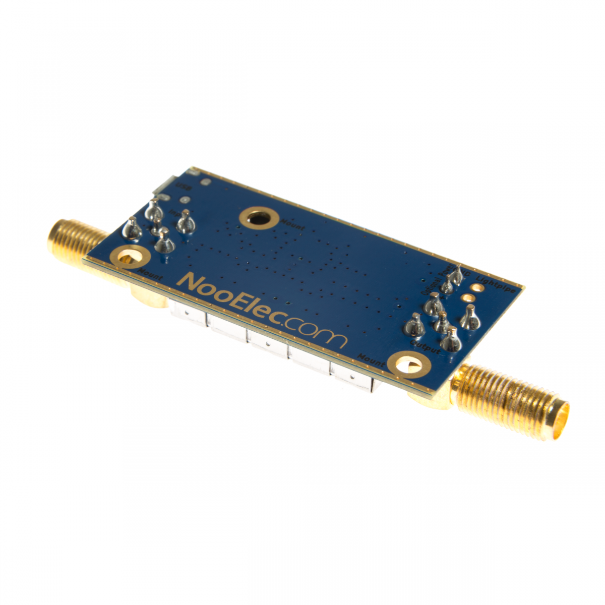
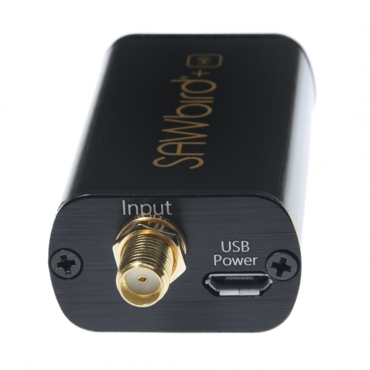
Nooelec has several SAWbird Low Noise Amplifiers ("LNA") for NOAA, the iridium and Inmarsat and other satellites, but the one shipped in this kit was the GOES flavor with a 1688 MHz Center Frequency: specifically the "premium" version with an aluminum enclosure. Note there's another bare board version.
The kit ships with a USB to power adapter. I had no idea if I am supposed to use it or not, as their web site claims:
"Each module allows for 3 different power options, but you should only power with one option at any given time! The recommended power input through the SMA output port (for bias-tee capable SDRs like the NESDR SMArTee XTR) is 3V-5V DC".
As the NESDR SMArTee XTR was also part of the kit, I assumed the power adapter is superfluous. However the web site also states "Our recommendation is the NESDR SMArTee XTR v2, which contains a bias-tee capable of powering the SAWbird GOES module with bias power". Not a single one of the nesdr xtr items made any mention of a "V2". There's one that looks similar, a Nooelec NESDR SMArt XTR SDR - Premium RTL-SDR w/ Extended Tuning Range, Aluminum Enclosure, 0.5PPM TCXO, SMA Input and another that looks exactly the same, but is labeled as Nooelec NESDR SMArTee XTR SDR - Premium RTL-SDR w/ Extended Tuning Range, Aluminum Enclosure, Bias Tee, 0.5PPM TCXO, SMA Input. (note that it mentions the "bias tee") I'm hoping the Amazon description of "The NESDR SMArTee XTR SDR unit will automatically feed the LNA through a built-in always-on Bias-T" is accurate and this will actually power the SAWbird.
Update: yes, it does! The power adapter is not needed; it's a bonus!
"There is no need to use the external power option. We opted to include the cable as it allows for easier use for customers who might want to use a different SDR for decoding than what came in the bundle" -- Nooelec Support
The SAWbird was initially equally frustrating; an SMA connector on each end with absolutely no indication of which end is input and which is output.
Update: Apparently somehow my SAWbird snuck through QA missing the silkscreen (perhaps that makes it a Collector's Edition?)

There's a poor quality picture on the Nooelec site that shows the bare board version has the input on the USB-side of the device:


Either use low loss coax cable or a USB extension cable to get the LNA and/or RTL-SDR out to the antenna. ... We strongly recommend using as little coax as possible after the LNA too. The SAWbird LNA doesn't have enough gain to push the signal through long runs of coax. If you're forced to use long runs of coax, use a secondary LNA. Preferably use a USB extension cable to reduce coax runs

After reading this blog, the Nooelec folks kindly responded with this helpful information:
"The snipped of text from the blog website you quoted is lacking a bit in detail. As general advice (for which it was intended) it's appropriate. However, the details matter. The required level of gain from the 1st & 2nd stage amplification on the SAWbird LNA will be contingent on the signal strength from the antenna (which is higher from our custom mesh than most normal installations). Further, it assumes a lossy cable (most people at best use RG58, which has insertion loss 4x higher than the included LMR400). Without getting into all the finer details, for most installations there will be about 10dB of headroom from the SAWbird before issues should start to crop up that might require a secondary LNA. That would be about 150' or more of LMR400 :) There should be zero difference if you try to decode at the output of the SAWbird vs. after the LMR400 included other than the gain on the SDR which would be more than sufficient to compensate for it. What matters more is the noise figure, which is dominated by the signal chain at and before the first LNA in the SAWbird. That is why we use high quality LMR400 on the antenna as well, and why that length is short, and why we mention it is crucial to keep the SAWbird as close to the antenna as possible." -- Nooelec support
sudo apt-get install -y \
    build-essential \
    cmake \
    git-core \
    libopencv-dev \
    zlib1g-dev \
    librtlsdr-dev

# be sure librtlsdr-dev is installed *before* compiling!

git clone --recursive https://github.com/pietern/goestools
cd goestools
mkdir build
cd build
cmake .. -DCMAKE_INSTALL_PREFIX=/usr/local
make
sudo make install
Yes, without the
sudo for make install, I saw this error:
  Install the project...
-- Install configuration: "RelWithDebInfo"
CMake Error at cmake_install.cmake:41 (file):
  file cannot create directory: /usr/local/share/goestools.  Maybe need
  administrative privileges.


make: *** [Makefile:140: install] Error 1
[demodulator]
# mode = "lrit"
mode = "hrit"
source = "rtlsdr"

# The section below configures the sample source to use.
#
# You can leave them commented out to use the default values for the
# demodulator mode you choose ("lrit" or "hrit"). To use and configure
# any of them, uncomment the section below, and change the demodulator
# source field to match the source you want to use.
#

# [airspy]
# frequency = 1694100000
# gain = 18

[rtlsdr]
frequency = 1694100000
sample_rate = 2000000
gain = 30
bias_tee = true

# [nanomsg]
# connect = "tcp://1.2.3.4:5005"
# receive_buffer = 2097152
# sample_rate = 2400000

[costas]
max_deviation = 200e3

# [clock_recovery.sample_publisher]
# bind = "tcp://0.0.0.0:5002"
# send_buffer = 2097152

[quantization.soft_bit_publisher]
bind = "tcp://0.0.0.0:5001"
send_buffer = 1048576

[decoder.packet_publisher]
bind = "tcp://0.0.0.0:5004"
send_buffer = 1048576

# The demodulator stats publisher sends a JSON object that describes
# the state of the demodulator (gain, frequency correction, samples
# per symbol), for every block of samples.
#[demodulator.stats_publisher]
#bind = "tcp://0.0.0.0:6001"

# The decoder stats publisher sends a JSON object for every packet it
# decodes (Viterbi corrections, Reed-Solomon corrections, etc.).
[decoder.stats_publisher]
bind = "tcp://0.0.0.0:6002"

# The monitor can log aggregated stats (counters, gauges, and
# histograms) to a statsd daemon. Because this uses UDP, you can keep
# this enabled even if you haven't setup a statsd daemon yet.
[monitor]
statsd_address = "udp4://localhost:8125"
Then run
goesrecv -c goes.conf -v -i 1
Note if you see an error:
Invalid downlink type: then you forgot to uncomment the hrit or lrit in the [demodulator] section of the config file. I opened Issue #101 to perhaps address this for others.
For reference, if the receiver is getting no data (such as the case when sitting in the house on the kitchen floor for me during initial setup), the output looks like this: pi@raspberrypi:~ $ goesrecv -c goes.conf -v -i 1
Detached kernel driver
Found Elonics E4000 tuner
Disabled direct sampling mode
[E4K] PLL not locked for 0 Hz!
Allocating 15 zero-copy buffers
2020-11-08T22:29:39Z [monitor] gain: 3.99, freq: 39.0, omega: 8.166, vit(avg): 2167, rs(sum): 0, packets: 0, drops: 6
2020-11-08T22:29:40Z [monitor] gain: 4.57, freq: -7.6, omega: 8.166, vit(avg): 2205, rs(sum): 0, packets: 0, drops: 12
2020-11-08T22:29:41Z [monitor] gain: 4.59, freq: 26.5, omega: 8.166, vit(avg): 2182, rs(sum): 0, packets: 0, drops: 11
2020-11-08T22:29:42Z [monitor] gain: 4.60, freq: 7.4, omega: 8.167, vit(avg): 2194, rs(sum): 0, packets: 0, drops: 12
2020-11-08T22:29:43Z [monitor] gain: 4.61, freq: -13.3, omega: 8.167, vit(avg): 2179, rs(sum): 0, packets: 0, drops: 11
2020-11-08T22:29:44Z [monitor] gain: 4.62, freq: -41.2, omega: 8.167, vit(avg): 2186, rs(sum): 0, packets: 0, drops: 12
2020-11-08T22:29:45Z [monitor] gain: 4.60, freq: -16.9, omega: 8.167, vit(avg): 2194, rs(sum): 0, packets: 0, drops: 11
^CSignal caught, exiting!
2020-11-08T22:29:46Z [monitor] gain: 4.58, freq: -27.7, omega: 8.167, vit(avg): 2185, rs(sum): 0, packets: 0, drops: 2
Reattached kernel driver
Many of the blogs seemed to make a big deal about leveling, having accurate compass, and other positioning issues. I don't think any of that is essential. The only thing really important is stability. I did buy an inexpensive angle locator on Amazon:

pi@raspberrypi:~ $ goesrecv -c goes.conf -v -i 1
Detached kernel driver
Found Elonics E4000 tuner
Disabled direct sampling mode
[E4K] PLL not locked for 0 Hz!
Exact sample rate is: 2000000.052982 Hz
Allocating 15 zero-copy buffers
2020-11-09T15:49:02Z [monitor] gain:  2.82, freq:    34.9, omega: 2.157, vit(avg): 1149, rs(sum):    0, packets:  0, drops: 40
2020-11-09T15:49:03Z [monitor] gain:  3.07, freq:    26.5, omega: 2.157, vit(avg): 1151, rs(sum):    0, packets:  0, drops: 54
2020-11-09T15:49:04Z [monitor] gain:  3.07, freq:    12.2, omega: 2.157, vit(avg): 1150, rs(sum):    0, packets:  0, drops: 56
2020-11-09T15:49:05Z [monitor] gain:  3.07, freq:    -4.6, omega: 2.157, vit(avg): 1172, rs(sum):    0, packets:  0, drops: 54
2020-11-09T15:49:06Z [monitor] gain:  3.08, freq:    -7.8, omega: 2.157, vit(avg): 1148, rs(sum):    0, packets:  0, drops: 57
2020-11-09T15:49:07Z [monitor] gain:  3.08, freq:    -1.2, omega: 2.157, vit(avg): 1166, rs(sum):    0, packets:  0, drops: 57
2020-11-09T15:49:08Z [monitor] gain:  3.08, freq:    13.2, omega: 2.158, vit(avg): 1164, rs(sum):    0, packets:  0, drops: 51
2020-11-09T15:49:09Z [monitor] gain:  3.08, freq:    -9.9, omega: 2.157, vit(avg): 1143, rs(sum):    0, packets:  0, drops: 52
2020-11-09T15:49:10Z [monitor] gain:  3.08, freq:    32.7, omega: 2.158, vit(avg): 1217, rs(sum):    0, packets:  0, drops: 52
2020-11-09T15:49:11Z [monitor] gain:  3.09, freq:  -870.8, omega: 2.157, vit(avg):  821, rs(sum):   16, packets: 19, drops: 35
2020-11-09T15:49:12Z [monitor] gain:  3.09, freq: -2376.1, omega: 2.157, vit(avg):  199, rs(sum):   76, packets: 55, drops:  0
2020-11-09T15:49:13Z [monitor] gain:  3.09, freq: -2352.7, omega: 2.158, vit(avg):  196, rs(sum):   65, packets: 56, drops:  0
2020-11-09T15:49:14Z [monitor] gain:  3.09, freq: -2351.0, omega: 2.157, vit(avg):  196, rs(sum):   76, packets: 57, drops:  0
2020-11-09T15:49:15Z [monitor] gain:  3.09, freq: -2391.0, omega: 2.158, vit(avg):  195, rs(sum):   64, packets: 58, drops:  0
2020-11-09T15:49:16Z [monitor] gain:  3.09, freq: -2377.3, omega: 2.158, vit(avg):  199, rs(sum):   83, packets: 55, drops:  0
2020-11-09T15:49:17Z [monitor] gain:  3.10, freq: -2337.0, omega: 2.158, vit(avg):  197, rs(sum):   89, packets: 57, drops:  0
2020-11-09T15:49:18Z [monitor] gain:  3.09, freq: -2385.5, omega: 2.157, vit(avg):  195, rs(sum):   52, packets: 58, drops:  0
2020-11-09T15:49:19Z [monitor] gain:  3.09, freq: -2393.7, omega: 2.158, vit(avg):  196, rs(sum):   72, packets: 56, drops:  0
2020-11-09T15:49:20Z [monitor] gain:  3.10, freq: -2389.4, omega: 2.158, vit(avg):  196, rs(sum):  103, packets: 56, drops:  0
# Example configuration file for goesproc
#
# This tool is designed to run on streaming data (live or recorded)
# and product whatever is listed in this file. A single product can be
# processed multiple times (e.g. with different contrast curves,
# different scale, or different annotations) by listing multiple
# handlers for that same product.
#

# GOES-16 mesoscale region 1 imagery is stored at ./goes16/m1/YYYY-MM-DD
# The pattern specified in {time:XXX} is extrapolated using strftime(3).
# It can be used more than once if needed.
[[handler]]
type = "image"
origin = "goes17"
region = "m1"
dir = "./goes17/m1/{time:%Y-%m-%d}"

# GOES-17 full disk originals.
[[handler]]
type = "image"
origin = "goes17"
region = "fd"
dir = "./goes17/fd/{time:%Y-%m-%d}"

# GOES-16 full disk, channel 2, with contrast curve applied.
# The section [handler.remap] below applies to this handler.
[[handler]]
type = "image"
origin = "goes17"
region = "fd"
channels = [ "ch02" ]
directory = "./goes16/fd/{time:%Y-%m-%d}"
filename = "{filename}_contrast"
sudo goesproc -c ~/goesproc.conf --subscribe tcp://127.0.0.1:5004
- rtl-sdr.com GOES 16/17 and gk 2a weather satellite reception comprehensive tutorial
- Receive GOES-16 and GOES-17 Images with a Raspberry Pi and RTL-SDR dongle
- www.dishpointer.com
- usradioguy.com
- pietern.github.io/goestools
- goestools - A minimal LRIT/HRIT receiver
- goestools installation
- goestools goesrecv; see ./etc/goesrecv.conf
- goestools goesproc
- Designing false colors for goes-r hrit
- xrit decoder
- SatNOGS Rotator v3
- CIMSS Satellite Blog - GOES-17 arrives at its GOES-West position of 137.2º W longitude