Showing posts with label VisualMicro. Show all posts

Friday, June 12, 2020

Arduino MKR WiFI 1010 Burning Bootloader from Visual Studio with Atmel Ice

The last time I used my Arduino MKR WIFI 1010 was way back when I wrote a blog about SWD Debugging the Arduino MKR-WiFi-1010 with Atmel ICE. I was at least kind enough to leave myself a note that once the Microchip Atmel Ice was used, the bootloader would need to be burned again to program the board over the serial port. Unfortunately the link was not very helpful. Perhaps the contents changed. In any case, I was not able to use the Ardunio IDE to burn the bootloader.

Wow, I tried searching the Arduino forums, and some of the folks there are pretty harsh with people asking simple questions. Either the answer to them was "don't burn the bootloader" or "read the fine manual". I didn't even bother asking. Instead I'm posting this solution, as yes, sometimes you really do need to burn the bootloader, and yes, I did RTFM (and still didn't find what I was looking for).

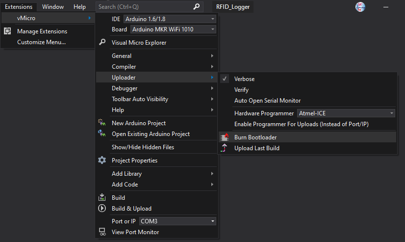
My prior blog includes all the pics on connections and such. The only thing needed is this information on how to burn the bootloader from within Visual Studio using the Visual Micro Arduino Extension. Once the Atmel ICE is connected, a fresh bootloader is just a couple of clicks away:


Menu selection for burning a fresh bootloader on the Arduino MKR Wi-Fi 1010 Board
A successful load should have an output like this:

Burning a new bootloader
Burning bootloader to board 'Arduino MKR WiFi 1010' using 'Atmel-ICE'
Erase Pattern: 
Bootloader Pattern: "{path}/{cmd}" {bootloader.verbose} -s "{path}/share/openocd/scripts/" -f "{runtime.platform.path}/variants/{build.variant}/{build.openocdscript}" -c "telnet_port disabled; init; halt; at91samd bootloader 0; program {{{runtime.platform.path}/bootloaders/{bootloader.file}}} verify reset; shutdown"
C:\Users\gojimmypi\AppData\Local\arduino15\packages\arduino\tools\openocd\0.9.0-arduino6-static\bin\openocd.exe -d2 -s "C:\Users\gojimmypi\AppData\Local\arduino15\packages\arduino\tools\openocd\0.9.0-arduino6-static/share/openocd/scripts/" -f "C:\Users\gojimmypi\AppData\Local\arduino15\packages\arduino\hardware\samd\1.6.20/variants/mkrwifi1010/openocd_scripts/arduino_zero.cfg" -c "telnet_port disabled; init; halt; at91samd bootloader 0; program {{C:\Users\gojimmypi\AppData\Local\arduino15\packages\arduino\hardware\samd\1.6.20/bootloaders/mkrwifi1010/samd21_sam_ba_arduino_mkrwifi1010.bin}} verify reset; shutdown"
Open On-Chip Debugger 0.9.0-g932ec70 (2017-02-15-12:34)
Licensed under GNU GPL v2
For bug reports, read
 http://openocd.org/doc/doxygen/bugs.html
debug_level: 2
Info : only one transport option; autoselect 'swd'
adapter speed: 500 kHz
adapter_nsrst_delay: 100
cortex_m reset_config sysresetreq
Info : CMSIS-DAP: SWD  Supported
Info : CMSIS-DAP: JTAG Supported
Info : CMSIS-DAP: Interface Initialised (SWD)
Info : CMSIS-DAP: FW Version = 01.27.0082
Info : SWCLK/TCK = 1 SWDIO/TMS = 1 TDI = 1 TDO = 1 nTRST = 0 nRESET = 1
Info : CMSIS-DAP: Interface ready
Info : clock speed 500 kHz
Info : SWD IDCODE 0x0bc11477
Info : at91samd21g18.cpu: hardware has 4 breakpoints, 2 watchpoints
target state: halted
target halted due to debug-request, current mode: Thread 
xPSR: 0x81000000 pc: 0x00004aac msp: 0x20007fa8
target state: halted
target halted due to debug-request, current mode: Thread 
xPSR: 0x81000000 pc: 0x00000b80 msp: 0x20007ffc
** Programming Started **
auto erase enabled
Info : SAMD: partitioning the first flash page into 8 subpages
Info : SAMD MCU: SAMD21G18A (256KB Flash, 32KB RAM)
wrote 8192 bytes from file C:\Users\gojimmypi\AppData\Local\arduino15\packages\arduino\hardware\samd\1.6.20/bootloaders/mkrwifi1010/samd21_sam_ba_arduino_mkrwifi1010.bin in 0.869252s (9.203 KiB/s)
** Programming Finished **
** Verify Started **
verified 7992 bytes in 0.676364s (11.539 KiB/s)
** Verified OK **
** Resetting Target **
Done burning bootloader.
Burn complete
shutdown command invoked


That's it! Once the bootloader has been installed, the MKR WiFI 1010 can once again be programmed over the serial port.

If problems are encountered while programming, try pressing the reset button on the board. Keep in mind that this causes the USB device to go away and come back. So if there's a VM Workstation running, there may be a prompt to connect the "new" device to host or virtual machine. The delay in answering that can also cause programming to fail.

Edit: If any problems are encountered seeing the device as a serial port after developing with the Atmel ICE, try loading up a blank program in release mode with the Atmel Studio and then burning the bootloader fresh:


/*Begining of Auto generated code by Atmel studio */
#include <Arduino.h>

/*End of auto generated code by Atmel studio */

//Beginning of Auto generated function prototypes by Atmel Studio
//End of Auto generated function prototypes by Atmel Studio

void setup() {
  // put your setup code here, to run once:
}

void loop() {
  // put your main code here, to run repeatedly:
  delay(1000);
}


Saturday, June 1, 2019

ULX3S and Visual Micro in Visual Studio 2019

This blog is a walk-though using the Visual Micro Arduino IDE in Visual Studio 2019 to program the ESP32 on the Radiona ULX3S. For more information on the ULX3S see my Day 1 intro, Using ujprog on WSL or MinGW, and Notes on ulx3s FPGA: Yosys, Verilog, VHDL, vhdl2vl (Convert VHDL to Verilog). Here's the ULX3S with the SPIDriver.

ULX3S with SPIDriver board
There are some brief online instructions for manually installing Visual Micro, or you can follow along here, using the VisualMicro example for the ULX3Son GitHub:

In Visual Studio 2019, click on Extensions - Manage Extensions.


Select "online" in the left pane and type "Arduino" in the search box:


Note the 5 stars reviews from hundreds of users. Yes, it is a very cool extension. :)

Next, click on the "Download" button. You'll need to restart Visual Studio 2019.

Be sure to wait for the VSIX installer screen! The first time I did this, I simply launched Visual Studio right away, and the Visual Micro Extension was no where to be found! Before launching Visual Studio, you should see this screen:


Then after a warning about system changes, this prompt:


Click the "Modify" button to continue. Upon completion, there should be a message "Modifications Complete"


When Visual Studio is next launched, click on "Create a new project"


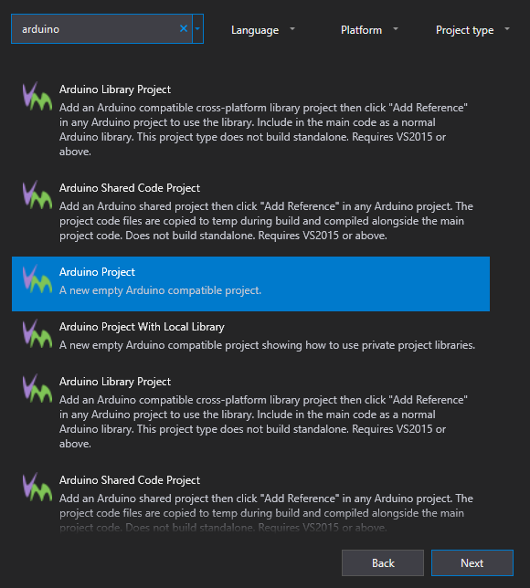
There are many project types, so type "Arduino" in the search box:


Select "Arduino Project" and click the Next button.


Give the project a name, and a location to store it. In this case, I am saving it in my ULX3S examples fork directory, to create a pull request to the official ULX3S Examples.

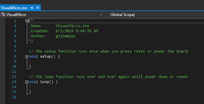
After clicking  the "Create" button, a familiar Arduino-style code template is created, with the setup() and loop() functions:


So that's the easy part. Now things get more interesting. The ESP32 on the ULX3S sits behind the FPGA chip. This means the only way to program the ESP32, is to have code on the ULX3S that performs a "pass through" function of external physical pins to the ESP32 pins through the FPGA.

schematic showing the ESP32 to FPGA connections


Fortunately, the ULX3S typically ships with the pass-though FPGA app already loaded. If not, the FPGA source code can be found here. Note there are three different versions: the Diamond VHDL that emard wrote, a Diamond Verilog that I converted from emard's VHDL, and finally an Open Source Verilog version that uses yosys and nextpnr. (hm, it looks like from the most recent comments I need to get the open source version working properly - I'll need to look into that)

If you are not ready to jump into the synthesis of FPGA bit files yet, you can use the passthru image file passthru_ulx3s_v20_12k.bit and load it onto the ESP32 using the ujprog tool. If you don't feel like building your own, there's a copy of both the bin directory.


if NOT EXIST c:\workspace mkdir c:\workspace
git clone https://github.com/gojimmypi/ulx3s-examples.git c:\workspace\ulx3s-examples
c:
cd \workspace\ulx3s-examples\VisualMicro\bin\
.\ujprog.exe passthru.bit


If "Cannot find JTAG cable" is encountered, remember that WSL is still not supporting native USB drivers. If you are using the Windows executable version and you see that message try changing the ULX3S drivers back to FTDI particularly if you don't see your ULX3S in the Ports (COM & LPT) container in device manager. WSL can be finicky, and even have different results whether executing from a Linux directory or DOS (e.g. /mnt/c/). And yes, native Windows executable files can be launched from WSL! cool.

Visual Studio seemed to have defaulted to all the correct values for me (I'm note sure if perhaps it remembered values from Visual Studio 2017) Here they are for reference:


Of particular interest is ensuring the proper COM port is selected, near the bottom of the settings list. I didn't see the actual ESP32 device listed (WROOM-32), so I used the ESP32 Dev Module setting.

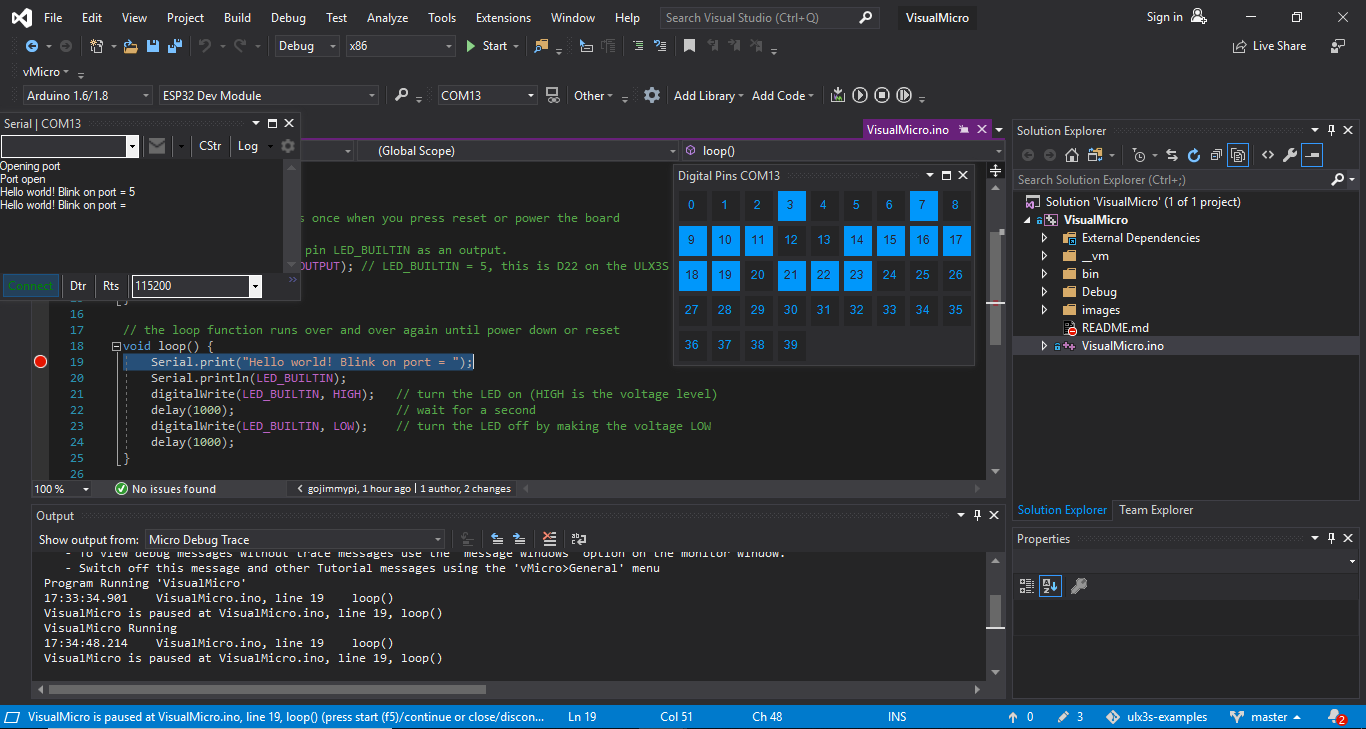
Once the pass through FPGA binary has been successfully uploaded, the simplest way to compile and upload the Arduino code via Visual Micro is to press F5 or the big green "start" button! That's it!

Note that one of the amazing things about the Visual Micro IDE, is they have implemented a debugger that does not require a hardware JTAG device! Here's my ULX3S ESP32 paused at a breakpoint:


Now onto that SPI Driver! Stay tuned for more....


Sunday, July 15, 2018

Pushing a button. From afar. With LoRa.

This blog entry is about pushing a button. Seems simple enough, eh? Except when the button you want to press is very far from where you are physically located... say, when there's a remote gate control well out of sight and out of range for the remote. Oh, and it is also too far to have any network connectivity. What to do?

My plan is to use LoRa to communicate from an M5Stack console to a distant LoRa32u4, each equipped with a LoRa module; essentially push the button of the remote from afar! The actual pysical button push on the M5Stack will essentially be "sent" (via LoRa message) to the remote 32u4 which will then trigger the actual remote control transmitter. The working prototype is shown here:


How to get there: The first thing needed is to disassemble the remote and determine how it normally works. The remote I am using is a Somfy TR2 similar to this one that can control two different devices. Upon disassembly, the first thing we see is those two buttons each with 4 pins. The buttons appear to be very similar to this Grayhill Gull Wing 95C06C3RAT at Mouser as documented here. Note that although there are 4 pins, it is simply a SPST switch:

Photo credit: Grayhill spec sheet

I confirmed both visually and with an ohmmeter that indeed I have a similar switch and proceeded to connect some external wires to it:

Somfy remote switch wiring

If you look closely, I took the time to wrap the wire around the pin of the switch to make a good mechanical connections, while being careful not to touch any other circuit. It would probably be a good idea to use some hot melt glue and affix the wires to the pc board.

Here, Green is a ground (all 4 pins, 2 from each switch); Orange is BP1 and Yellow is BP2. The top of the battery is labeled as being the positive side. The entire metal surface here is at 3.3V:


This turned out to be an extremely handy arrangement for me: the entire device could essentially be the "load" for an NPN transistor circuit!

Putting an ammeter between either the orange or yellow pins to ground, I found about 0.3mA that would otherwise flow though the button (or a transistor).

Looking at the specs for the 2N3904, the max collector current is a whopping 200mA  max, well over a couple orders of magnitude for what we'll need:


And for a collector current of (we'll round up) to 0.5 mA, we'll have a minimum gain of around 60 to 80 (let's pick a gain of 70 for discussion-sake):


We'll need a base current of around  (0.005A / 70) =  0.0714 mA;  For the current-limiting base resistor, we'll thus need: 3.3v / (0.0000714) ~= 40K ohms. I didn't have a 40K handy, but I did have a bunch of 20K ohm resistors laying around, so I'll use that. It is still well within spec, and will certainly account for any gain drift or degradation.

Our button-pressing supplement thus looks like this (shown for BP1, but the same for BP2):
Note that this circuit will allow our 32u4 to control the remote via a GPIO pin. Fortunately the remote is also smart enough to turn itself off - if for some reason the button remains pressed so that the battery does not drain (such as being poked by your keys in your pocket). In our case: regardless of the state of the pin during power up (or application crash) the battery will be preserved.
The manual prototype looks like this:


Note the red wire to drive the base of the transistor is stuffed into the battery holder for the picture. Once in operation this red wire will instead be the GPIO output from the 32u4.

Next, we need to make sure the remote is actually working! As mentioned in my previous blogs on M5Stack LoRa Range Issues as well as this fun project using OpenWRT on EA3500 with RTL-SDR Stream, I have an inexpensive NooElec SDR, that is simply amazing - particularly given the price! With this hardware, and the some software, we'll be able to "see" the remote signal.

The last time I used Cubic SDR, it was working fine. Today? Nothing. Erg. Gotta love Windows. App starts, no complaints, but no signal. A little bit of googling, and there's the Quick Start Guide. First thing I noticed was mention of my old friend, zadig. Sure enough: during one of the the Windows updates, the default driver was changed for some bizarre reason. Here's the screen just before correcting it:


And tada! Exit Cubic SDR (no need, at least for me, to reboot computer)... relaunch Cubic SDR app... then pressing Start for my RTL2832U device:


The waterfall immediately starts! Press the button on the remote a few times, and we can see the pulse at about 433.5 MHz. Notice the messy side-band noise, as well as someone else continuously transmitting at about 432 MHz:


I have the source code for all this on GitHub here: https://github.com/gojimmypi/LoRa-GPIO (note there are also Development and M5-RadioHead branches, but after a bunch of GitHub fussing, I think the master branch is now up to date). The projects are VisualMicro extensions to Visual Studio, but I suspect the Arduino code would work just fine in the Arduino IDE.

More to come...

Sunday, March 4, 2018

M5Stack LoRa Range Improvement


Last month I started working on a project to control GPIO pins on a device (relatively) very far away using LoRa technology. Most of the showstopper problems seem to have been resolved. Well, at least getting the RadioHead code working on the M5Stack. This blog entry continues on that topic...

TL;DR
  • VisualMicro Arduino projects in Visual Studio, using 32u4 (see also Adafruit 32u4) and M5Stack - both over LoRa.
  • M5Stack RSSI is a solid RSSI strength of 10 points worse than the exact same code on 32u4 which has the exact same RA-02 AI-Thinker LoRa device.
  • Recall from previous blog, LoRa RST and IRQ are reversed. (RST is actually GPIO36 input only; unusable). Otherwise it would have been: Beep = LoRa reset. 
  • M5Stack Speaker (GPIO25) is shared with LoRa Interrupt. (beep = interrupt?)
  • The M5Stack display shares the NSS pin with the LoRa module. (poke registers with care!)
  • The receiver and transmitter need to be configured EXACTLY the same for best range (more than just the same frequency); but this was not the problem with our poor RSSI
  • My LoRa-GPIO project and required RadioHead and M5Stack libraries merged to master on GitHub
  • When updating library (include) code, Visual Studio apparently does not look at file dates and may use previous compiled code; clean project after library changes.
The latest working (although not very pretty) Very Remote Lora-GPIO Control and Monitoring Project code has been merged onto my master branch.

I've merged my M5Stack development branch back to my RadioHead master branch. This was a "Squash and Merge". Normally I like to keep the history... but as the RadioHead owners prefer a single patch file, perhaps this will be better. Time will tell. History is still in the branch.

I've submitted a PR to Adafruit at their request, as well as well as sent a patch file to Mike at ReadioHead. Ok, this is weekend and evening working, certainly not some of my best polished work. I need to go back and clean things up.

My M5Stack library fork is, and has been up to date on the master branch. (no branches)

The main LoRa-GPIO solution contains several projects as noted in the GitHub readme. These are all Arduino-style projects using the really awesome VisualMicro add-in for Visual Studio.

As a side note, while working on this - I found what appears to be GitHub branch-to-branch compares not working properly.  (if it *does* work properly and I'm simply not doing it correctly, please let me know)

I've been reading through the ARRL Ham Radio License manual. I don't know if I will actually get a ham license, but wow - what a great book this is to cover the essentials of what you need to know for RF communications (such as the LoRa for this project). Although I had a ton of classes in college covering a wide variety of electronics, electromagnetism, communications, even an entire class on antenna theory... this ARRL book contains a lot of relatively straightforward, every-day language on the practical essentials of radio frequency communication - all in one place. The ARRL web site also has some excellent resources. Ok, there's also pretty much NO math, NO theory: Just useful facts. So this is certainly not a book for how or why or how to apply to new problem. Still, it is a quite good book. Highly recommended & would make a great gift for someone new to the field.

So on to the testing... now that I have the RadioHead drivers working, I actually went back to the M5Stack example code (Sandeep drivers renamed M5LoRa). Recall that I have the RadioHead drivers on a remote 32u4 sending LoRa packets. Here's the sample code for the M5Stack receiver (Arduino: File - Examples - M5Stack - Modules - LoRa - LoRaReceiver) :


#include 
#include 

#define LORA_CS_PIN   5
#define LORA_RST_PIN  26
#define LORA_IRQ_PIN  36

void setup() {
  
  M5.begin();

  // override the default CS, reset, and IRQ pins (optional)
  LoRa.setPins(LORA_CS_PIN, LORA_RST_PIN, LORA_IRQ_PIN); // set CS, reset, IRQ pin
  Serial.println("LoRa Receiver");
  M5.Lcd.println("LoRa Receiver");

  // frequency in Hz (433E6, 866E6, 915E6)
  if (!LoRa.begin(433E6)) {
    Serial.println("Starting LoRa failed!");
    M5.Lcd.println("Starting LoRa failed!");
    while (1);
  }

  // LoRa.setSyncWord(0x69);
  Serial.println("LoRa init succeeded.");
  M5.Lcd.println("LoRa init succeeded.");
}

void loop() {
  // try to parse packet
  int packetSize = LoRa.parsePacket();
  if (packetSize) {
    // received a packet
    Serial.print("Received packet: \"");
    M5.Lcd.print("Received packet: \"");

    // read packet
    while (LoRa.available()) {
      char ch = (char)LoRa.read();
      Serial.print(ch);
      M5.Lcd.print(ch);
    }

    // print RSSI of packet
    Serial.print("\" with RSSI ");
    Serial.println(LoRa.packetRssi());
    M5.Lcd.print("\" with RSSI ");
    M5.Lcd.println(LoRa.packetRssi());
  }
}

This code writes to  both the M5Stack display as well as the serial port. The display is cool as I don't need to remember to disconnect the serial port when reprogramming. HOWEVER: You may recall from my previous blog that the M5Stack display *and* LoRa module share the NSS (slave select) pin. That simply sounds dangerous (and indeed I observed some display oddities), so I put M5Stack LoRa to sleep when writing to the display.

The shocking thing here is that there's up to a difference of TEN in RSSI values as compared to using the RadioHead drivers. (RSSI 36 vs 26). As this is a log scale, that's a 10x difference in power! Now - this is not to say that the Sandeep library has a problem just because it is polling rather than using interrupts. It is a matter of default configuration. I picked apart the RadioHead control register libraries and added a note about the matching importance:


When printing the register values from the Sandeep (M5LoRa) library, (move the readRegister from the private to public section)...

    Serial.print("0x");
    Serial.print(LoRa.readRegister((uint8_t )0x1d),HEX);
    Serial.print(", 0x");
    Serial.print(LoRa.readRegister((uint8_t )0x1e),HEX);
    Serial.print(", 0x");
    Serial.print(LoRa.readRegister((uint8_t )0x26),HEX);


There's a SINGLE BIT different (CRC not enabled!):  0x72, 0x70, 0x4 - alas that didn't seem to make much of a substantial difference in RSSI values. I supposed I had expected different error coding, spreading factor, or some other obvious difference.

I confirmed the running values of RadioHead cinfig registers are also 0x72, 0x70, 0x4 - but the RSSI is typically -25 whereas the Sandeep (M5Lora) drivers report an RSSI of typically -35!

So the next thing is: how to each of them calculate RSSI?


Well, the Sandeep / M5Lora library does this:

int LoRaClass::packetRssi()
{
  return (readRegister(REG_PKT_RSSI_VALUE) - (_frequency < 868E6 ? 164 : 157));
}

float LoRaClass::packetSnr()
{
  return ((int8_t)readRegister(REG_PKT_SNR_VALUE)) * 0.25;
}

But the RadioHead library does this:
// Remember the last signal to noise ratio, LORA mode
// Per page 111, SX1276/77/78/79 datasheet
_lastSNR = (int8_t)spiRead(RH_RF95_REG_19_PKT_SNR_VALUE) / 4;

// Remember the RSSI of this packet, LORA mode
// this is according to the doc, but is it really correct?
// weakest receiveable signals are reported RSSI at about -66
_lastRssi = spiRead(RH_RF95_REG_1A_PKT_RSSI_VALUE);
// Adjust the RSSI, datasheet page 87
if (_lastSNR < 0)
 _lastRssi = _lastRssi + _lastSNR;
else
 _lastRssi = (int)_lastRssi * 16 / 15;
if (_usingHFport)
 _lastRssi -= 157;
else
 _lastRssi -= 164;


Grr... So ok, the difference in RSSI appears to be simply a different calculation.  The real test is: how far away can the units be and still communicate? I'm still happy I have the RadioHead libraries working. In my opinion is is clearly the superior code.

So reference check: after all the code changes, let's try same units: 32u4 to 32u4. Cleaned project, full rebuild. RSSI value is -19 or -20! Rechecking the M5Stack, RSSI is -27.  So even with the same codebase and same calcs, the M5Stack LoRa has a poorer RSSI value. Using an external battery power source and the value improves to RSSI = -24.

So, as mentioned about - I've been reading about real world antennas, so perhaps the M5Stack antenna has an issue. Well, I tried that as well, replacing the internal antenna with one of those external antennas - identical to the one on the 32u4. Still there's a discrepancy in RSSI values between the two devices.

What else? Ok, so there's a speaker in the M5Stack. Poking around with that, defined in:

libraries\M5Stack\src\utility\Config.h

there's a declaration:

// BEEP PIN
#define SPEAKER_PIN 25

Ah yes, GPIO25, our friend. The LoRa interrupt pin.  (sigh)

So perhaps all the extras in the M5Stack are indeed causing a problem. I tried to disable a few things  such as the speaker init, but no luck. I do however, have another Console (without display) app that is specifically targeted for the 32u4, but with the magic of simply changing platforms in the IDE, can be recompiled and sent to the M5Stack!  RSSI about that same at -27 (ranging from -23 to -29).  Replace with the exact same code on the 32u4 and the RSSI is a full 10 points better at -17.  (10x improvement in signal strength!).

I tried another M5Stack unit with a different LoRa module. Same result.

So at this point, I really believe it is a hardware issue. I've been unable to get a copy of the schematic for the M5Stack LoRa module, However the 32u4 has a pin connection diagram here.

As soon as hardware is questioned - the first thing to do is of course add some capacitors! I added a 10uF and a 10pf cap directly to the power input to the RA-02.


In the pic, you can see I fished a new, external antenna along with the new caps. And ya, I got a little close to the side of the M5 Lora module.

Additionally I added a shield (aluminum foil sandwiched between two layers of clear packing tape) to both sides of the LoRa module. After all - there is an ESP32 microprocessor buzzing away just on the other side of the PCB!


The first field test was a relative success! I more than doubled the original range! Ok, so I didn't actually test after each change, so I don't know exactly which was the most effective in extending the range.

Note the Semtech site has a bunch of LoRa resources, including this cool LoRa calculator (I will include in my GitHub repository in the docs container, in case the link to Semtech ever breaks.


Note that I am currently transmitting at 125kHz. Lowering this increases range! Lower this to about 15.6kHz and you get another 10db in "link performance". (in theory).

Overall I am quite happy with the result. Ok, I'm not seeing multi-kilometer ranges. But that's also line-of-sight. My transmitter is on the kitchen table - with the entire garage between it and the M5Stack receiver. Next test will be from line of site.

The super exciting thing is I have a prototype from the kind folks at M5Stack arriving in the mail soon for the next potential version of the LoRa module. I am quite interested in seeing how well it performs.

Stay tuned for my next blog where I work on the prototype V2 LoRa modules with its own embedded ATMEGA328.


Resources, Inspiration, Credits, and Other Links:

Monday, February 12, 2018

M5Stack LoRa Range Issues

Investigating 32u4 to M5Stack LoRa poor range issues; Background information & initial tool setup.

Well, after my last post regarding the fascinating world of FPGA programming, I really thought this next post would continue on that topic. I really want to try out Luke's tiny FPGA board. Alas I've encountered another issue on a project that warrants sharing and someplace for me to keep my notes.


TL;DR

  • Misc details and notes on LoRa
  • VisualMicro ESP32 USB Debugging caused by new driver version
  • NESDR issue with SDR software and driver install
  • LoRa Range issue still unresolved, stay tuned for part 2


Late last year, I finally decided to buy a couple of "DIYmall LoRa32u4 LORA RA-02 Module Development Board Long Range Communication 1KM LiPo Atmega328 SX1278 with IPEX Antenna for Arduino" devices when Amazon had one of their "Lightening Deal of the Day" sales. Not to be confused with LoRaWAN - these are simple serial-type broadcast devices but with very long range. Getting them to talk to each other was ridiculously easy mainly thanks to the great Adafruit Feather 32u4 with LoRa Radio Module tutorial and sample code.

Perhaps there's some software to do LoRaWAN with these (if anyone knows, let me know ) - however I don't have any service providers nearby and the gateways are expensive.

edit 2/18/18: here's a video on creating a LoRa gateway:


By the time my LoRa modules arrived, I had forgotten the title explicitly called out the "RA-02 Module". In hindsight, I'm surprised the Adafruit code worked at all, given their description naming their LoRa device as a Adafruit Feather 32u4 LoRa (RFM9x).  Apparently the RA-02 and RF95 libraries are "close enough" - as my 32u4 appears to have the exact same RA-02 module as used on the M5Stack LoRa module. (I wonder what, exactly is on the Adafruit device?)

Which reminds me: be sure to check the frequency of the respective LoRa devices: they need to match not only each other, but also be allowed in respective county of use!

  (source: RF Wireless World)

After having the proof of concept working with the two 32u4 devices (RadioHead RFM95 libraries)  - which I was able to show them working hundreds of meters apart through very obstructed signal path and certainly not a straight line-of-site (e.g. hill, buildings, trees, etc)... I thought it would be cool to have a display module on one end, controlling the GPIO's on the other.

Some time ago, I had ordered an ESP32-based M5Stack so I decided to use this for a "console" along with their LoRa Module to talk to a very remote 32u4. Seems simple enough in concept, eh? Ha! Nothing is ever as easy as is is supposed to be.

First, the M5Stack core library uses different Sandeep Mistry LoRa drivers. (see also github) Thinking that "LoRa is LoRa", I assumed that they would work together. Indeed the workbench test was a complete success the first time.

However, the first real field test was a disaster. Taking the dog for a walk with an M5Stack connected to USB battery pack in hand, I expected to be tweeting success far from home. I was barely out of WiFi range across the street when the M5Stack stopped receiving messages from the 32u4. Certainly a long way from kilometer LONG Range.

As it turns out, KongDuino recently left a rather interesting blog review of the M5Stack and LoRa modules. It would seem that I'm not the only one with LoRa range problems. If it was easy, it wouldn't be any fun - right?

Note that the 32u4 devices use so little power, that the Anker portable power supply turns off after a few minutes - perhaps thinking nothing is actually connected. Perhaps a USB hub or something might help for a road trip with it.

I've posted my code on GitHub under a project called LoRa-GPIO. This is a pitiful hack of sample code, but an otherwise operational proof of concept of the 32u4 transmitting a signal for the M5Stack to receive and display.

So to investigate the range issues, we'll need some tools such as break-point debugging and signal analysis.

Note for anyone using VisualMicro for development (like me). If any problems are encountered debugging the ESP32, be sure to check the CP210x USB driver version - particularly just after Windows Updates. There's apparently a known problem with recent drivers not working, Simply select (or install as needed) an older version to fix:


Ok, so anytime there's a signal transmission issue at hand, it is helpful to have some visualization tools. I have the inexpensive Nooelec Smart SDR on hand.

See Using SDR Sharp Quick Start Guide. Download Windows SDR Package from https://airspy.com/download/  Need to disable new security feature that prohibits unsigned drivers.

bcdedit /set testsigning on

Reboot. To turn off:
bcdedit /set testsigning off

Even running zadig as administrator, I was unable to change drivers. So ok, I guess I needed to download new driver installer from the Nooelec Getting Started.  Windows is brutal; it completely removed the prior SDR drivers I had installed and working. Grr,,,

SDR Sharp had complained about the Visual Studio 2015 C++ runtime not being able to be installed (I have Visual Studio 2017 installed)... so rather than fuss with that, I installed the CubicSDR 0.2.2 software also located at the bottom of the Nooelec Getting Started with NESDR page.

Note there's an entire CubicSDR web site, and the most recent version appears to be v0.2.3 released in January of this year (2018) complete with source code on GitHub.

Once finally installed, the LoRa signal can be visualized:


So, ok.. I've fussed with Visual Studio debugging, SDR software install, and typing up all these notes and most of the day has flown by. No progress today on the actual problem of poor LoRa range. Clearly a part two is due and coming soon...


Saturday, July 15, 2017

ESP8266 OTA Water Pressure Flow Monitor

I've been working with the ESP8266 for quite some time now, but I've only programmed it while it was sitting right at my desk and having it plugged into a USB port. A variety of projects that I have developed have always been convenient to test. However my latest creation involves water. I could not quite imagine how I'd test this at my workbench, nor did it seem very appealing to be programming in the garage. In the summer. In California.

Today I discovered how amazingly simply it is to do "Over The Air" (OTA) programming of the ESP8266, thanks to this really cool Random Nerd Tutorial - ESP8266 OTA Updates with Arduino IDE | Over the Air.

I've been wanting to hook up these pressure and flow sensors that I found on ebay to monitor water usage. I also needed a few fittings that I found on Amazon. I purchased there as I could return them free, no hassle if there was a problem; I had a dreadful time finding anything like this at the local hardware store. I needed this Stainless Steel 316 Cast Pipe Fitting, Hex Bushing, MSS SP-114, 3/4" X 1/4" NPT Male X Female adapter for the pressure sensor, and thisStainless Steel 316 Cast Pipe Fitting, Tee, Class 150, 3/4" NPT Female so that I could hook up both the pressure sensor and flow meter at the same time. The result is a male-female connector that I can slip inline.


You may wonder why I would be interested in something as boring as water pressure. Well, not long ago I discovered my pressure regulator quietly failed. Let's just say I will never again ignore water pressure! There's a reason for the regulator - and the maximum ratings on the water heater. The water softener. The reverse osmosis system.... For only about 10 bucks, you can keep an eye on pressure the  manual, old-school way with this Rain Bird P2A Water Pressure Test Gauge - but what fun is that when there's an electronic gizmo option?

I admit I had some temporary disappointment at the beginning of Step 3 of the OTA tutorial, where I expected to see the the esp8266-xxxxxx at my_esp_ip_address port. I did not. I was not able to see this until exiting and restarting Arduino. No worries, onward!

The next step is to program in some other environment other than the Arduino IDE. I am quite addicted to Visual Studio. I have both the VisualGDB and VisualMicro add-ins. I like VisualMicro in that I can take Arduino code samples and immediately start coding. I have yet to figure out how to do this with VisualGDB. The last time I asked about it, there was no hope on the horizon for Arduino support in VisualGDB,

Initially, it appears there's no option other than the Arduino IDE to actually program OTA. I could find nothing in Visual Studio where it could "see" the pseudo-serial-over-ethernet port. Ha! But fortunately there's a verbose output from the Arduino IDE. In particular this last command shown before uploading:

python.exe C:\Users\gojimmypi\AppData\Local\Arduino15\packages\esp8266\hardware\esp8266\2.3.0/tools/espota.py -i 192.168.1.103 -p 8266 --auth= -f C:\Users\GOJIMM~1\AppData\Local\Temp\arduino_build_690448/sketch_jul15a.ino.bin

The important thing here is that there's a python script called espota.py that sends a binary file to the OTA client. (side note: simply genius implementation in less than 9K!) The paths are crazy long, but the command is essentially this:

python.exe espota.py -i 192.168.1.101 -p 8266 --auth= -f yourfile.bin
Pasting the same OTA sample code into a VisualMicro Ardino Project in Visual Studio... then compiling, shows the output path of the binary:
"C:\Users\gojimmypi\AppData\Local\arduino15\packages\esp8266\tools\esptool\0.4.9/esptool.exe" -eo "C:\Users\gojimmypi\AppData\Local\arduino15\packages\esp8266\hardware\esp8266\2.3.0/bootloaders/eboot/eboot.elf" -bo "C:\Users\gojimmypi\AppData\Local\Temp\VMBuilds\WaterPressureFlow\esp8266_generic\Release/WaterPressureFlow.ino.bin" -bm qio -bf 40 -bz 4M -bs .text -bp 4096 -ec -eo "C:\Users\gojimmypi\AppData\Local\Temp\VMBuilds\WaterPressureFlow\esp8266_generic\Release/WaterPressureFlow.ino.elf" -bs .irom0.text -bs .text -bs .data -bs .rodata -bc -ec
This one is an even longer and crazier command. Really the only thing we are interested in is where the output file is stored. In my case it is:
"C:\Users\gojimmypi\AppData\Local\Temp\VMBuilds\WaterPressureFlow\esp8266_generic\Release/WaterPressureFlow.ino.bin"
There's some sloppy use of mixing forward and back-slashes; for Windows I highly recommend editing them and making them all backslashes.

So now using the Arduino OTA command with the destination of the VisualStudio binary, we can develop OTA with Visual Studio! My command looks like this:
python.exe C:\Users\gojimmypi\AppData\Local\Arduino15\packages\esp8266\hardware\esp8266\2.3.0\tools\espota.py -i 192.168.1.103 -p 8266 --auth= -f C:\Users\gojimmypi\AppData\Local\Temp\VMBuilds\WaterPressureFlow\esp8266_generic\Release\WaterPressureFlow.ino.bin
I thought perhaps this could be fully automated by adding the command to the Post Build Event in VisualStudio:
 
However I was unable to get the command to trigger. This article on Specifying Build Events at Microsoft seems to indicate that last option "In Excluded From Build, specify Yes if you do not want the event to run". However my prompt is "Use in Build". I tried both Yes and No - and the OTA command appears to never have been attempted. Perhaps this is because it is a VisualMicro project. No worries, still just as easy to use the up-arrow in a DOS box to re-upload freshly compiled code.

I'm still hopeful that I will be able to do this in a single build operation. The VisualMicro site has a page indicating that build events are now supported. I've submitted a question to their support forum to find out. It appears the only option is a "quite convoluted and difficult to test" option. Hopefully they have the built-in events working.
And indeed YES! Just minutes after posting my question on the forum, I received a response! A simple matter of right-click on project - add - Add Local Board.txt with this text

# WaterPressureFlow build property overrides
#
# local project board.txt overrides
network.port=8266
as described here. So no need for a convoluted solution or manual specification of build event. It just works! Be sure to press "enter" when entering an IP address for serial port (otherwise it won't stick). Now the VisualMicro "Build & Upload" sends OTA data. Sweet. :)


See also: https://github.com/gojimmypi/mqttFlowESP8266 and Updating adafruit.io ESP8266 MQTT code


Find gojimmypi at gojimmypi.github.io

I'm currently working on my new blog home at  gojimmypi.github.io After implementing a variety of features such as dark mode , syntax hi...