Sunday, December 20, 2020

iCE40 FPGA Programming with WSL and Open Source Tools

Here are some notes on programming the Lattice Semiconductor iCE40 FPGA chip.

This is supplementary information to the awesome learn-fpga walk-through by @BrunoLevy01 that I worked on a couple of weekends ago, specifically the IceStick Tutorial, but for Windows and WSL instead of Linux.


The default Windows drivers are FTDIBUS. Unfortunately this driver will typically NOT work to program the iCE40. If later changed with Zadig, they can be returned to the Windows default by right-clicking on the item in Device Manager and selecting "Update Driver". Choosing "Search Automatically for Driver" should assign the default FTDIBUS drivers. (either that, or just wait for Windows to arbitrarily change it back when you least expected it)

It may be best to start with plugging the device directly into the computer, rather than using a hub. Sometimes there are "issues". 

To program the iCE40 with iceprog assign the libusbK drivers with Zadig:  

Oddly, I found that I needed to assign the libusbK drivers to BOTH Interface 0 and Interface 1 in order to be able to successfully program the iCE40. Further, not only did the drivers need to be installed on both interfaces, but after doing so - I had to unplug (wait a few seconds) and plug in the device for successful programming when the drivers were first changed.

The drivers will almost certainly revert back to the FTDI default at Windows update time, and perhaps arbitrary other times as well.

It seems that the WinUSB drivers also work for successful programming.

Note that nether the libusbK nor the WinUSB drivers will show up as a COM port in Windows, so no TTY connection with something like putty.

Assigning the USB Serial drivers, and the Lattice shows up as a COM port. But here, iceprog will not see the iCE40 to program it.

Program only on the first interface:  iceprog.exe -I A femtosoc.bin

Attempting to program on the second interface gets stuck here at the erase step:

$ /mnt/c/Users/gojimmypi/.icestudio/apio/packages/toolchain-ice40/bin/iceprog.exe -I A femtosoc.bin
init..
cdone: high
reset..
cdone: low
init..
cdone: high
reset..
cdone: high
Extended Device String Length is 0xFF, this is likely a read error. Ignorig...
flash ID: 0xFF 0xFF 0xFF 0xFF
file size: 32220
erase 64kB sector at 0x000000..


This is what it looks like when iceprog cannot find the USB device:
0 $ /mnt/c/Users/gojimmypi/.icestudio/apio/packages/toolchain-ice40/bin/iceprog.exe -I A femtosoc.bin
init..
Can't find iCE FTDI USB device (vendor_id 0x0403, device_id 0x6010 or 0x6014).
ABORT.

If Zadig was used to assign the USBSER driver, the above step may not work. Assign it to something else (recommended libusbK) and then try again.

WinUSB devices show up here in Device Manager: 


Changing Interface 1 appears to also change Interface 0. However the reverse is not true. Thus it is best to assign drivers to Interface 1 first.


Reminder: When assigning new drivers, it is usually best to unplug and re-plug the iCE40 stick after drivers are changed with Zadig, otherwise iceprog may fail.

Note that for a "real" Ubuntu - in this case on a VM on a Windows host, the iCEStick shows up as 3 devices, no fussing with Zadig or anything else:


Here, the make terminal just works:


I was unable to persuade WSL, with any sort of Zadig drivers, to recognize the iCEStick in terminal mode. If it was a plain TTY terminal, it might have worked, but since I am using WSL1 and the target is /dev/ttyUSB1 - I don't this this would ever work on WSL1. Perhaps with WSL2 native USB support?


Monday, November 9, 2020

GOES17 Satellite Image Reception with Nooelec Kit and Raspberry Pi

These are my (admittedly sometimes long and rambling) thoughts and more of a "review" of my recent purchase. I'm planning a second blog with just the details on setting up. Stay tuned.

My first "full disk" image was pulled from the GOES-17 Satellite on November 8!

I've been wanting to learn about satellite reception and SDR signal processing for quite some time. I have pretty much zero experience here. I've never even owned a TV satellite dish. This is certainly not my first SDR product from Nooelec. I first received their NESDR Smart RTL-SDR as a birthday present several years ago, and really enjoyed setting up OpenWRT on EA3500 with RTL-SDR Stream

I was inspired to buy the Nooelec kit on Amazon after reading about it on the RTL SDR blog, in particular the quite excellent online tutorial on GOES 16/17 Weather Satellite Reception. This was somewhat of a gamble, as I bought mine before any of the reviews on Amazon. (there are now several 5 star reviews!)

I first tried 137.2W GOES-S (GOES-17).

See also the reddit PSA PSA: What you need to know about GOES-13:

The hardware and software requirements for successful GOES-13 decoding are completely different from GOES-16/17 and all other L-Band geostationary weather satellites, do not expect the same setup that works for LRIT/HRIT to work with GOES-13

Update: The USRADIOGUY GOES Satellite Imagery Reception is a great place for info, that would have been quite helpful had I known about it when I started. 

Note that if you go looking for those PDF files at the end in the resources section, they are no longer available. I contacted NOAA support and they responded within 24 hours and even included the files! I submitted an upstream PR, but it looks like there has not been much activity recently. I have a copy in my WIP GOES-Setup docs.

When the kit arrived, I thought the dish was all one piece, as it arrived in one of the biggest Amazon boxes I've ever received. Is the box half full or half empty? I think it is twice as big as it needs to be, just the right size for two of them:


The out-of-box experience was a bit frustrating. There was pretty much no documentation included on assembly or operation. The only thing included was a thank-you card with a link to start.nesdr.com which as of the time if this writing, just redirected to nooelec.com/store/qs with nothing more than basic information on how install the drivers. 

Update: there's now a helpful Set-Up Instructions page on the Nooelec site, and they've added a setup picture on the Amazon product page:


The "driver download" is actually just an old (Version 2.3 from 2017) of Zadig, not actually the drivers. The Nooelec web site was also annoying, as well: Google Chrome would do this annoying oscillation when hovering over the little question mark icons to view the pictures. It was exceptionally frustrating to just view the web picture. Within 24 hours of my message to support, the Nooelec folks fixed that!

In any case, there's not much to do in Windows anyhow, as the XRIT Decoder for GOES Satellite is another $125, as noted on Twitter; note in particular the link to A minimal LRIT/HRIT receiver. But I wanted to at least see if everything was working in Windows.

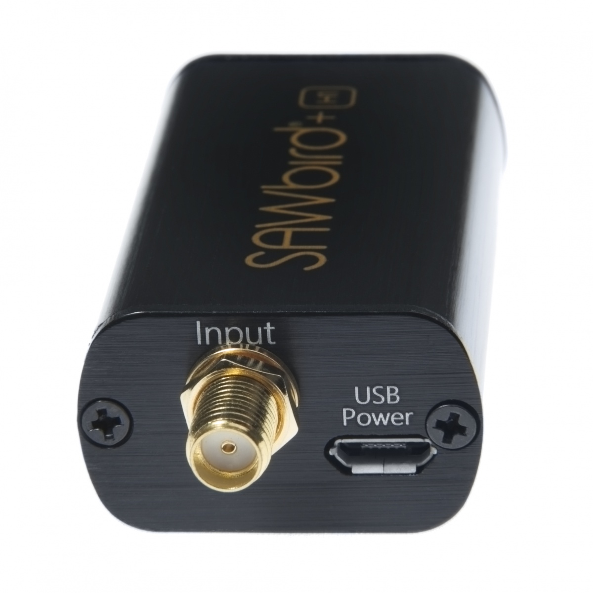
Nooelec has several SAWbird Low Noise Amplifiers ("LNA") for NOAA, the iridium and Inmarsat and other satellites, but the one shipped in this kit was the GOES flavor with a 1688 MHz Center Frequency: specifically the "premium" version with an aluminum enclosure. Note there's another bare board version.

The kit ships with a USB to power adapter. I had no idea if I am supposed to use it or not, as their web site claims:

 "Each module allows for 3 different power options, but you should only power with one option at any given time! The recommended power input through the SMA output port (for bias-tee capable SDRs like the NESDR SMArTee XTR) is 3V-5V DC". 

As the NESDR SMArTee XTR was also part of the kit, I assumed the power adapter is superfluous. However the web site also states "Our recommendation is the NESDR SMArTee XTR v2, which contains a bias-tee capable of powering the SAWbird GOES module with bias power". Not a single one of  the nesdr xtr items made any mention of a "V2". There's one that looks similar, a Nooelec NESDR SMArt XTR SDR - Premium RTL-SDR w/ Extended Tuning Range, Aluminum Enclosure, 0.5PPM TCXO, SMA Input and another that looks exactly the same, but is labeled as Nooelec NESDR SMArTee XTR SDR - Premium RTL-SDR w/ Extended Tuning Range, Aluminum Enclosure, Bias Tee, 0.5PPM TCXO, SMA Input. (note that it mentions the "bias tee") I'm hoping the Amazon description of "The NESDR SMArTee XTR SDR unit will automatically feed the LNA through a built-in always-on Bias-T" is accurate and this will actually power the SAWbird.

Update: yes, it does! The power adapter is not needed; it's a bonus!

"There is no need to use the external power option.  We opted to include the cable as it allows for easier use for customers who might want to use a different SDR for decoding than what came in the bundle" -- Nooelec Support

The SAWbird was initially equally frustrating; an SMA connector on each end with absolutely no indication of which end is input and which is output. 

Update: Apparently somehow my SAWbird snuck through QA missing the silkscreen (perhaps that makes it a Collector's Edition?)

There's a poor quality picture on the Nooelec site that shows the bare board version has the input on the USB-side of the device:


As those labels are barely visible, it is at least reassuring to see the output label on the other end:


Although I suppose it makes sense to have power input on the antenna input site of the SAWbird, it ends up being the opposite end of the USB input on the SMArtee device. So in the case of no bias-tee, you have power at opposite ends.

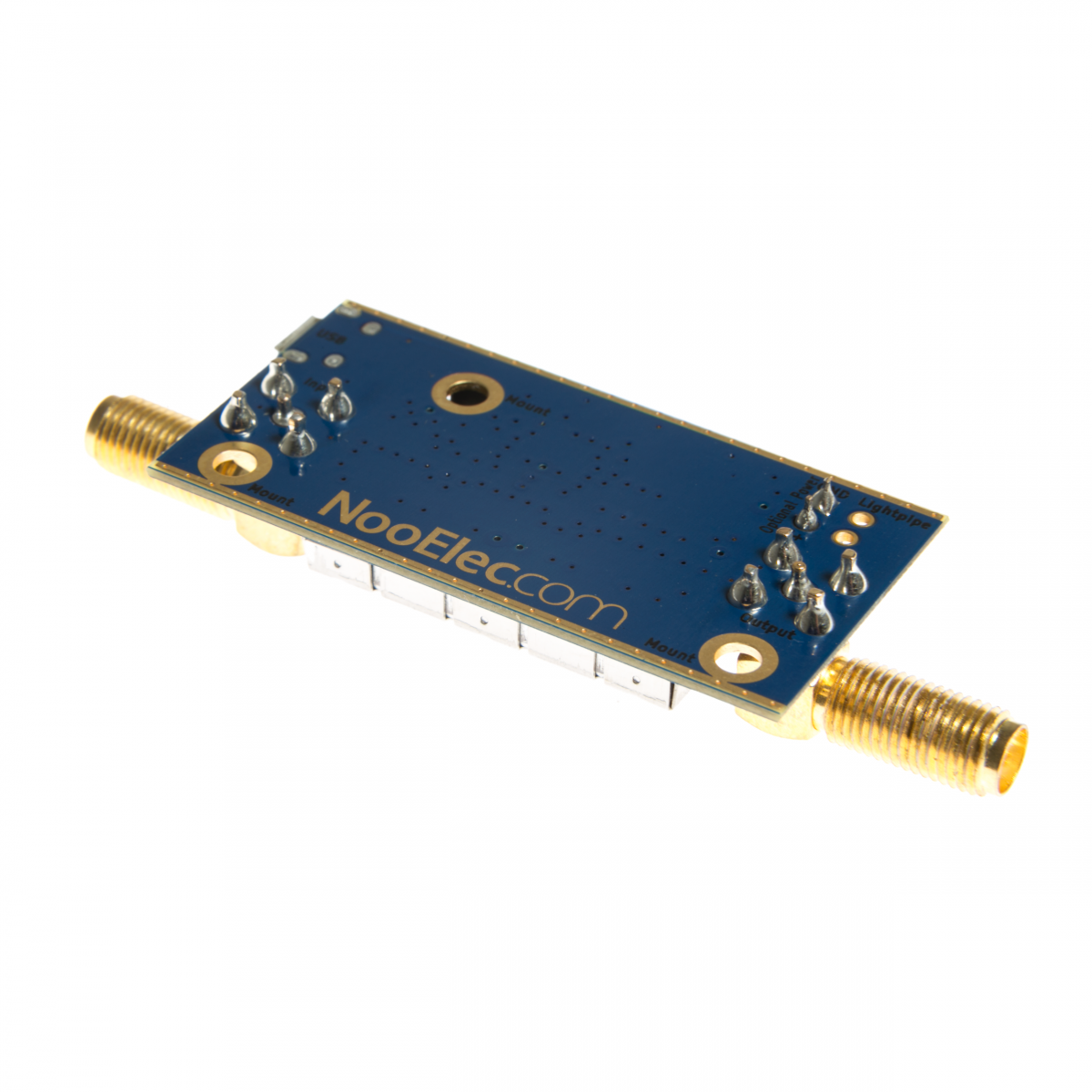
Update: the kind support folks at Nooelec pointed out that there should be a silkscreen as on the Hydrogen Line SAWbird as shown in this image from their product web page, confirming that yes the input from the antenna is on the USB port end:


On the topic of input, see the RTL SDR blog, in particular the part:

Either use low loss coax cable or a USB extension cable to get the LNA and/or RTL-SDR out to the antenna.  ... We strongly recommend using as little coax as possible after the LNA too. The SAWbird LNA doesn't have enough gain to push the signal through long runs of coax. If you're forced to use long runs of coax, use a secondary LNA. Preferably use a USB extension cable to reduce coax runs

I would certainly have preferred a long stretch of active USB cable instead of 10m (30 feet) of LMR400 cable. Although yes the LMR400 is "low loss", it is certainly not "no loss". This Pasternack Product Listing, and in particular the datasheet indicates that there's fairly significant loss in the 1.7GHz range and shown from this snip of Times Microwave Systems graph:


After reading this blog, the Nooelec folks kindly responded with this helpful information:

"The snipped of text from the blog website you quoted is lacking a bit in detail.  As general advice (for which it was intended) it's appropriate.  However, the details matter.  The required level of gain from the 1st & 2nd stage amplification on the SAWbird LNA will be contingent on the signal strength from the antenna (which is higher from our custom mesh than most normal installations).  Further, it assumes a lossy cable (most people at best use RG58, which has insertion loss 4x higher than the included LMR400).  Without getting into all the finer details, for most installations there will be about 10dB of headroom from the SAWbird before issues should start to crop up that might require a secondary LNA.  That would be about 150' or more of LMR400 :)  There should be zero difference if you try to decode at the output of the SAWbird vs. after the LMR400 included other than the gain on the SDR which would be more than sufficient to compensate for it.  What matters more is the noise figure, which is dominated by the signal chain at and before the first LNA in the SAWbird.  That is why we use high quality LMR400 on the antenna as well, and why that length is short, and why we mention it is crucial to keep the SAWbird as close to the antenna as possible." -- Nooelec support


On to Raspberry Pi setup... See my prior blog on Raspberry Pi Headless Setup

Do not install the RTLSDR USB hardware into an already powered-on Raspberry Pi! The RPi crashes from the power surge. Yes, I learned this the hard way. I never trust the SD card after such a crash, so I started over.

I ran the install for the Raspberry Pi. It takes quite some time to download and install everything:

sudo apt-get install -y \
    build-essential \
    cmake \
    git-core \
    libopencv-dev \
    zlib1g-dev \
    librtlsdr-dev

# be sure librtlsdr-dev is installed *before* compiling! 

git clone --recursive https://github.com/pietern/goestools
cd goestools
mkdir build
cd build
cmake .. -DCMAKE_INSTALL_PREFIX=/usr/local
make
sudo make install    
  

Yes, without the sudo for make install, I saw this error:
  
Install the project... -- Install configuration: "RelWithDebInfo" CMake Error at cmake_install.cmake:41 (file): file cannot create directory: /usr/local/share/goestools. Maybe need administrative privileges. make: *** [Makefile:140: install] Error 1


There are two components to receiving satellite images, that I ran in separate putty sessions. One is the goesrecv which, as the name implies, is the data stream receiver. The other key software component that runs completely separately, either on the same RPi or another computer, is the goesproc which actually processes the data stream and turns it into images. Amazing images.

Note the "source" just refers to one of the other sections in the config file with parameter settings:

[demodulator]
# mode = "lrit"
mode = "hrit"
source = "rtlsdr"

# The section below configures the sample source to use.
#
# You can leave them commented out to use the default values for the
# demodulator mode you choose ("lrit" or "hrit"). To use and configure
# any of them, uncomment the section below, and change the demodulator
# source field to match the source you want to use.
#

# [airspy]
# frequency = 1694100000
# gain = 18

[rtlsdr]
frequency = 1694100000
sample_rate = 2000000
gain = 30
bias_tee = true

# [nanomsg]
# connect = "tcp://1.2.3.4:5005"
# receive_buffer = 2097152
# sample_rate = 2400000

[costas]
max_deviation = 200e3

# [clock_recovery.sample_publisher]
# bind = "tcp://0.0.0.0:5002"
# send_buffer = 2097152

[quantization.soft_bit_publisher]
bind = "tcp://0.0.0.0:5001"
send_buffer = 1048576

[decoder.packet_publisher]
bind = "tcp://0.0.0.0:5004"
send_buffer = 1048576

# The demodulator stats publisher sends a JSON object that describes
# the state of the demodulator (gain, frequency correction, samples
# per symbol), for every block of samples.
#[demodulator.stats_publisher]
#bind = "tcp://0.0.0.0:6001"

# The decoder stats publisher sends a JSON object for every packet it
# decodes (Viterbi corrections, Reed-Solomon corrections, etc.).
[decoder.stats_publisher]
bind = "tcp://0.0.0.0:6002"

# The monitor can log aggregated stats (counters, gauges, and
# histograms) to a statsd daemon. Because this uses UDP, you can keep
# this enabled even if you haven't setup a statsd daemon yet.
[monitor]
statsd_address = "udp4://localhost:8125"


Then run
goesrecv -c goes.conf -v -i 1
  

Note if you see an error: Invalid downlink type: then you forgot to uncomment the hrit or lrit in the [demodulator] section of the config file. I opened Issue #101 to perhaps address this for others. 

For reference, if the receiver is getting no data (such as the case when sitting in the house on the kitchen floor for me during initial setup), the output looks like this:
pi@raspberrypi:~ $ goesrecv -c goes.conf -v -i 1
Detached kernel driver
Found Elonics E4000 tuner
Disabled direct sampling mode
[E4K] PLL not locked for 0 Hz!
Allocating 15 zero-copy buffers
2020-11-08T22:29:39Z [monitor] gain:  3.99, freq:    39.0, omega: 8.166, vit(avg): 2167, rs(sum):    0, packets:  0, drops:  6
2020-11-08T22:29:40Z [monitor] gain:  4.57, freq:    -7.6, omega: 8.166, vit(avg): 2205, rs(sum):    0, packets:  0, drops: 12
2020-11-08T22:29:41Z [monitor] gain:  4.59, freq:    26.5, omega: 8.166, vit(avg): 2182, rs(sum):    0, packets:  0, drops: 11
2020-11-08T22:29:42Z [monitor] gain:  4.60, freq:     7.4, omega: 8.167, vit(avg): 2194, rs(sum):    0, packets:  0, drops: 12
2020-11-08T22:29:43Z [monitor] gain:  4.61, freq:   -13.3, omega: 8.167, vit(avg): 2179, rs(sum):    0, packets:  0, drops: 11
2020-11-08T22:29:44Z [monitor] gain:  4.62, freq:   -41.2, omega: 8.167, vit(avg): 2186, rs(sum):    0, packets:  0, drops: 12
2020-11-08T22:29:45Z [monitor] gain:  4.60, freq:   -16.9, omega: 8.167, vit(avg): 2194, rs(sum):    0, packets:  0, drops: 11
^CSignal caught, exiting!
2020-11-08T22:29:46Z [monitor] gain:  4.58, freq:   -27.7, omega: 8.167, vit(avg): 2185, rs(sum):    0, packets:  0, drops:  2
Reattached kernel driver
  

Many of the blogs seemed to make a big deal about leveling, having accurate compass, and other positioning issues. I don't think any of that is essential. The only thing really important is stability. I did buy an inexpensive angle locator on Amazon:


So the only thing I actually measured was the initial inclination of the dish boom - which btw is aluminum, so the magnetic feature didn't help much here. I pointed the dish in the general direction of the satellite as indicated for my location from www.dishpointer.com. Then I loaded up juice ssh on a mobile device (or you could take a laptop), and manually adjusted the dish to get the vit(avg) values as low as possible.

And don't be discouraged if all packets are initially dropped, it may take a bit of time for the signal to lock:
pi@raspberrypi:~ $ goesrecv -c goes.conf -v -i 1
Detached kernel driver
Found Elonics E4000 tuner
Disabled direct sampling mode
[E4K] PLL not locked for 0 Hz!
Exact sample rate is: 2000000.052982 Hz
Allocating 15 zero-copy buffers
2020-11-09T15:49:02Z [monitor] gain:  2.82, freq:    34.9, omega: 2.157, vit(avg): 1149, rs(sum):    0, packets:  0, drops: 40
2020-11-09T15:49:03Z [monitor] gain:  3.07, freq:    26.5, omega: 2.157, vit(avg): 1151, rs(sum):    0, packets:  0, drops: 54
2020-11-09T15:49:04Z [monitor] gain:  3.07, freq:    12.2, omega: 2.157, vit(avg): 1150, rs(sum):    0, packets:  0, drops: 56
2020-11-09T15:49:05Z [monitor] gain:  3.07, freq:    -4.6, omega: 2.157, vit(avg): 1172, rs(sum):    0, packets:  0, drops: 54
2020-11-09T15:49:06Z [monitor] gain:  3.08, freq:    -7.8, omega: 2.157, vit(avg): 1148, rs(sum):    0, packets:  0, drops: 57
2020-11-09T15:49:07Z [monitor] gain:  3.08, freq:    -1.2, omega: 2.157, vit(avg): 1166, rs(sum):    0, packets:  0, drops: 57
2020-11-09T15:49:08Z [monitor] gain:  3.08, freq:    13.2, omega: 2.158, vit(avg): 1164, rs(sum):    0, packets:  0, drops: 51
2020-11-09T15:49:09Z [monitor] gain:  3.08, freq:    -9.9, omega: 2.157, vit(avg): 1143, rs(sum):    0, packets:  0, drops: 52
2020-11-09T15:49:10Z [monitor] gain:  3.08, freq:    32.7, omega: 2.158, vit(avg): 1217, rs(sum):    0, packets:  0, drops: 52
2020-11-09T15:49:11Z [monitor] gain:  3.09, freq:  -870.8, omega: 2.157, vit(avg):  821, rs(sum):   16, packets: 19, drops: 35
2020-11-09T15:49:12Z [monitor] gain:  3.09, freq: -2376.1, omega: 2.157, vit(avg):  199, rs(sum):   76, packets: 55, drops:  0
2020-11-09T15:49:13Z [monitor] gain:  3.09, freq: -2352.7, omega: 2.158, vit(avg):  196, rs(sum):   65, packets: 56, drops:  0
2020-11-09T15:49:14Z [monitor] gain:  3.09, freq: -2351.0, omega: 2.157, vit(avg):  196, rs(sum):   76, packets: 57, drops:  0
2020-11-09T15:49:15Z [monitor] gain:  3.09, freq: -2391.0, omega: 2.158, vit(avg):  195, rs(sum):   64, packets: 58, drops:  0
2020-11-09T15:49:16Z [monitor] gain:  3.09, freq: -2377.3, omega: 2.158, vit(avg):  199, rs(sum):   83, packets: 55, drops:  0
2020-11-09T15:49:17Z [monitor] gain:  3.10, freq: -2337.0, omega: 2.158, vit(avg):  197, rs(sum):   89, packets: 57, drops:  0
2020-11-09T15:49:18Z [monitor] gain:  3.09, freq: -2385.5, omega: 2.157, vit(avg):  195, rs(sum):   52, packets: 58, drops:  0
2020-11-09T15:49:19Z [monitor] gain:  3.09, freq: -2393.7, omega: 2.158, vit(avg):  196, rs(sum):   72, packets: 56, drops:  0
2020-11-09T15:49:20Z [monitor] gain:  3.10, freq: -2389.4, omega: 2.158, vit(avg):  196, rs(sum):  103, packets: 56, drops:  0
  

# Example configuration file for goesproc
#
# This tool is designed to run on streaming data (live or recorded)
# and product whatever is listed in this file. A single product can be
# processed multiple times (e.g. with different contrast curves,
# different scale, or different annotations) by listing multiple
# handlers for that same product.
#

# GOES-16 mesoscale region 1 imagery is stored at ./goes16/m1/YYYY-MM-DD
# The pattern specified in {time:XXX} is extrapolated using strftime(3).
# It can be used more than once if needed.
[[handler]]
type = "image"
origin = "goes17"
region = "m1"
dir = "./goes17/m1/{time:%Y-%m-%d}"

# GOES-17 full disk originals.
[[handler]]
type = "image"
origin = "goes17"
region = "fd"
dir = "./goes17/fd/{time:%Y-%m-%d}"

# GOES-16 full disk, channel 2, with contrast curve applied.
# The section [handler.remap] below applies to this handler.
[[handler]]
type = "image"
origin = "goes17"
region = "fd"
channels = [ "ch02" ]
directory = "./goes16/fd/{time:%Y-%m-%d}"
filename = "{filename}_contrast"

  
Running in a second SSH session:
sudo goesproc -c ~/goesproc.conf --subscribe tcp://127.0.0.1:5004
    

Note that yes, I am using sudo with goesproc. Although it seemed to run without error otherwise, the files that it claimed to have saved were nowhere to be found.

To get the pictures off the Raspberry Pi, you can use pscp that comes with Putty.

That's only fun for the first few pictures, I suggest getting something like winscp.

Sunday, November 1, 2020

EA3500 OpenWRT WiFi to WiFi STA Routing

Setting up Cisco Linksys EA3500 as WiFi to WiFi (STA mode) to have wired ethernet clients instead of WiFi clients (as opposed to the typical AP mode). 

TL;DR; install OpenWRT; change Network - Interfaces IP address of EA3500; use wireless mode N, auto.

I want to connect my wired ethernet device, for example the Envox EEZ Bench Box 3 "Modular, open-source test & measurement chassis" to WiFi. Sounds simple enough...

Update: the above picture is not accurate unless router forwarding rules are manually applied.

In my prior blogs, I recorded some notes on setting up a Raspberry Pi as either a WiFi STA Router (not an AP!) to route local eth0 onto the wlan0 for WiFi-to-WiFi connection (most people do the reverse: hardwire a WiFi router to their ISP and use it as an access point routing wlan0 to eth0). The routed solution has the benefit of an arbitrary number of ethernet clients, but the disadvantage of being on a different network and requiring some manual routing configuration. An alternative solution used the clever wlan_kable app to instead bridge the local RPi eth0 onto the WiFi network. This is works much more gracefully with no manual routing config, but was limited to a single device. This was ok, as I only wanted by BenchBox3 to have WiFi network capability. However, I later experienced some oddities when downloading large automation scripts to the BB3. On to the next option: a "real" router.

I have an old Linksys EA3500 available. They can be found on ebay for around 10 bucks (cheaper than a Raspberry Pi!) Of course, the native firmware does not support using the WiFi radio as a client station. The first thing that comes to mind is WRT: either dd-wrt or OpenWRT. It seems that the dd-wrt solution will pretty much never happen, despite having support for a large number of routers. If it turns out you have one of those routers and want to use dd-wrt, be sure to read the Client Mode wiki.

The very first google search for OpenWRT EA3500 however, was a link to the OpenWRT firmware download page for the EA3500! Could it be that easy? Yes! I simply loaded the 19.07.04 Firmware OpenWRT Install and voila! OpenWRT on the EA3500!! 

This is not the first time I've used OpenWRT. See my prior blog on OpenWRT on EA3500 with RTL-SDR Stream.

If you don't know the password on the router, hold down the reset button for 30 seconds to factory reset (until the LED next to the power starts to blink). The default password is: admin

Upgrading from stock firmware is found under "Connectivity" (go figure).


Click on the "Choose file..." and select the OpenWRT file, and click "Start".


Note that if you are concerned about bricking your router, there are fallback options, and in particular I think the Tigard multi-protocol, multi-voltage tool for hardware hacking could be helpful for not only unbricking, but lots of other cool hardware hacking adventures.

For reference: OpenWRT also has an excellent EA3500 feature summary, copied here as we know things on the internet sometimes just vanish:

There's a wiki guide for OpenWRT: Connect to client Wi-Fi network. Alas I followed along multiple times and simply could not get my WiFi router to connect. Lesson #1: It won't tell you if you enter the wrong WiFi password for the AP you are trying to connect to as a STA client. It just won't work. (and will appear and disappear from the Network - Wireless "Associated Stations") Beyond that, the instructions were not completely clear for this router with various firewall settings, etc. Thus my notes are here:

As described at the beginning on the WRT wiki, if your local network is 192.168.1.x then the router interface needs to be changed to a different network, say 192.168.2.x; See Network - Interfaces:


Actually, I almost never leave a network default at 192.168.1.x as there will typically be a conflict such as this. Alas for this demo I was on a test network...

In my case, my PC was connected to the target wireless AP (referred to here as "your_SSID") and the EA3500 was plugged into my ethernet port. I disabled the WiFi on my PC that was on the same network (192.168.1.0) to configure the EA3500. After editing the IPv4 device address to some other network (e.g. 192.168.2.1), notice the defined network also changes. 


The wireless settings tab is also someplace that I was tripped up; Next, under Network - Wireless, click the scan button for Generic MAC80211 802.11bgn. (not the one ending in "an") Find your SSID and click the "Join Network" button and enter your SSID and pass phrase:. 


When saving, there will be a bit more config: leave mode set to "N" and change channel to "Auto".


Although previously pressing "save", it is not until you press the "Save & Apply" button:


That's it! Despite the wiki mentioning firewall settings, etc. It is not needed for basic functionality (you may still with to optimize and further secure the router). It is best to restart the BB3 and exit EEZ Studio as well before connecting with the new router.

Some other details:

Note the OpenWRT has SSH enabled by default:


See the luci essentials. Of particular interest are the /etc/config/uhttpd and /etc/config/luci configuration files for luci. See the other files in \etc\config for other config files:

Note that only 4 files are changed from the default install to get basic operational functionality:

/etc/config/dhcp
root@OpenWrt:~# cat /etc/config/dhcp

config dnsmasq
        option domainneeded '1'
        option boguspriv '1'
        option filterwin2k '0'
        option localise_queries '1'
        option rebind_protection '1'
        option rebind_localhost '1'
        option local '/lan/'
        option domain 'lan'
        option expandhosts '1'
        option nonegcache '0'
        option authoritative '1'
        option readethers '1'
        option leasefile '/tmp/dhcp.leases'
        option resolvfile '/tmp/resolv.conf.auto'
        option nonwildcard '1'
        option localservice '1'

config dhcp 'lan'
        option interface 'lan'
        option start '100'
        option limit '150'
        option leasetime '12h'
        option dhcpv6 'server'
        option ra 'server'
        option ra_management '1'

config dhcp 'wan'
        option interface 'wan'
        option ignore '1'

config odhcpd 'odhcpd'
        option maindhcp '0'
        option leasefile '/tmp/hosts/odhcpd'
        option leasetrigger '/usr/sbin/odhcpd-update'
        option loglevel '4'

/etc/config/firewall

root@OpenWrt:~# cat /etc/config/firewall

config defaults
        option syn_flood '1'
        option input 'ACCEPT'
        option output 'ACCEPT'
        option forward 'REJECT'

config zone
        option name 'lan'
        option input 'ACCEPT'
        option output 'ACCEPT'
        option forward 'ACCEPT'
        option network 'lan'

config zone
        option name 'wan'
        option input 'REJECT'
        option output 'ACCEPT'
        option forward 'REJECT'
        option masq '1'
        option mtu_fix '1'
        option network 'wan wan6 wwan'

config forwarding
        option src 'lan'
        option dest 'wan'

config rule
        option name 'Allow-DHCP-Renew'
        option src 'wan'
        option proto 'udp'
        option dest_port '68'
        option target 'ACCEPT'
        option family 'ipv4'

config rule
        option name 'Allow-Ping'
        option src 'wan'
        option proto 'icmp'
        option icmp_type 'echo-request'
        option family 'ipv4'
        option target 'ACCEPT'

config rule
        option name 'Allow-IGMP'
        option src 'wan'
        option proto 'igmp'
        option family 'ipv4'
        option target 'ACCEPT'

config rule
        option name 'Allow-DHCPv6'
        option src 'wan'
        option proto 'udp'
        option src_ip 'fc00::/6'
        option dest_ip 'fc00::/6'
        option dest_port '546'
        option family 'ipv6'
        option target 'ACCEPT'

config rule
        option name 'Allow-MLD'
        option src 'wan'
        option proto 'icmp'
        option src_ip 'fe80::/10'
        list icmp_type '130/0'
        list icmp_type '131/0'
        list icmp_type '132/0'
        list icmp_type '143/0'
        option family 'ipv6'
        option target 'ACCEPT'

config rule
        option name 'Allow-ICMPv6-Input'
        option src 'wan'
        option proto 'icmp'
        list icmp_type 'echo-request'
        list icmp_type 'echo-reply'
        list icmp_type 'destination-unreachable'
        list icmp_type 'packet-too-big'
        list icmp_type 'time-exceeded'
        list icmp_type 'bad-header'
        list icmp_type 'unknown-header-type'
        list icmp_type 'router-solicitation'
        list icmp_type 'neighbour-solicitation'
        list icmp_type 'router-advertisement'
        list icmp_type 'neighbour-advertisement'
        option limit '1000/sec'
        option family 'ipv6'
        option target 'ACCEPT'

config rule
        option name 'Allow-ICMPv6-Forward'
        option src 'wan'
        option dest '*'
        option proto 'icmp'
        list icmp_type 'echo-request'
        list icmp_type 'echo-reply'
        list icmp_type 'destination-unreachable'
        list icmp_type 'packet-too-big'
        list icmp_type 'time-exceeded'
        list icmp_type 'bad-header'
        list icmp_type 'unknown-header-type'
        option limit '1000/sec'
        option family 'ipv6'
        option target 'ACCEPT'

config rule
        option name 'Allow-IPSec-ESP'
        option src 'wan'
        option dest 'lan'
        option proto 'esp'
        option target 'ACCEPT'

config rule
        option name 'Allow-ISAKMP'
        option src 'wan'
        option dest 'lan'
        option dest_port '500'
        option proto 'udp'
        option target 'ACCEPT'

config include
        option path '/etc/firewall.user'


(my /etc/firewall.user had nothing extra)

/etc/config/network

root@OpenWrt:~# cat /etc/firewall.user
# This file is interpreted as shell script.
# Put your custom iptables rules here, they will
# be executed with each firewall (re-)start.

# Internal uci firewall chains are flushed and recreated on reload, so
# put custom rules into the root chains e.g. INPUT or FORWARD or into the
# special user chains, e.g. input_wan_rule or postrouting_lan_rule.
root@OpenWrt:~# cat /etc/config/network

config interface 'loopback'
        option ifname 'lo'
        option proto 'static'
        option ipaddr '127.0.0.1'
        option netmask '255.0.0.0'

config globals 'globals'
        option ula_prefix 'fdb2:e9f2:64b4::/48'

config interface 'lan'
        option type 'bridge'
        option ifname 'eth0.1'
        option proto 'static'
        option netmask '255.255.255.0'
        option ip6assign '60'
        option ipaddr '192.168.2.1'

config interface 'wan'
        option ifname 'eth1.2'
        option proto 'dhcp'

config interface 'wan6'
        option ifname 'eth1.2'
        option proto 'dhcpv6'

config switch
        option name 'switch0'
        option reset '1'
        option enable_vlan '1'

config switch_vlan
        option device 'switch0'
        option vlan '1'
        option ports '0 1 2 3 5t'

config switch_vlan
        option device 'switch0'
        option vlan '2'
        option ports '4 6t'

config interface 'wwan'
        option proto 'dhcp'


/etc/config/wireless

root@OpenWrt:~# cat /etc/config/wireless

config wifi-device 'radio0'
        option type 'mac80211'
        option hwmode '11g'
        option path 'mbus@f1000000/mbus@f1000000:pcie@82000000/pci0000:00/0000:00:01.0/0000:01:00.0'
        option htmode 'HT20'
        option channel 'auto'

config wifi-iface 'default_radio0'
        option device 'radio0'
        option network 'lan'
        option mode 'ap'
        option ssid 'OpenWrt'
        option encryption 'none'
        option disabled '1'

config wifi-device 'radio1'
        option type 'mac80211'
        option channel '36'
        option hwmode '11a'
        option path 'mbus@f1000000/mbus@f1000000:pcie@82000000/pci0000:00/0000:00:02.0/0000:02:00.0'
        option htmode 'HT20'
        option disabled '1'

config wifi-iface 'default_radio1'
        option device 'radio1'
        option network 'lan'
        option mode 'ap'
        option ssid 'OpenWrt'
        option encryption 'none'

config wifi-iface 'wifinet2'
        option ssid 'your_SSID'
        option device 'radio0'
        option mode 'sta'
        option key 'your_SSID_password_in_plain_text'
        option network 'wwan'
        option encryption 'psk2'


Of course, see that line: option mode 'sta' near the bottom of wireless settings: The key to all of this!


Sunday, October 25, 2020

Raspberry Pi Bridge eth0 to wlan0 with wlan_kabel

I spent a ridiculous amount of time trying to persuade native Raspberry Pi OS to bridge the local ethernet port onto the WiFi segment. (turns out it is apparently not possible) 

My intention is having a remote device such as my Envox BB3 programmable power supply with only a wired ethernet connection, connect to my WiFi segment so that I can use EEZ Studio without needing to plug the BB3 into a wired ethernet port. The connection is the same as before:


In my prior blog, I came up with a somewhat brute-force method of setting up a local DHCP server and using dnsmasq. However, as brute force methods go, it was also neither a very graceful nor flexible solution.

While surfing the internet looking for alternatives, there was one person that casually mentioned "you can also try wlan_kabel". This turned out to be a ridiculously cool solution!

Starting with my default headless Raspberry Pi setup, install git and clone escitalopram's wlan_kabel. You'll need the MAC address of the device to use; the BB3 shows this on the ethernet settings screen:


sudo apt-get install git
git clone https://github.com/escitalopram/wlan_kabel.git
cd wlan_kabel
make

# the magic (showing the example MAC address from the docs)
# you'll need to put your own address here:
sudo ./wlan_kabel wlan0 eth0 74:69:69:2d:30:11

That's it! It just works. There are of course limitations (one device connected to Raspberry Pi eth0 port).

To run wlan_kabel at boot time, put this in /etc/rc.local :
(/home/pi/wlan_kabel/wlan_kabel wlan0 eth0 74:69:69:2d:30:11 > /dev/null 2>&1) &
Don't forget to use your own MAC address, and be sure to include the training ampersand.

This is a vastly more graceful solution. Just plug in the RPi and connect to the IP address shown, in my case 192.168.1.114 then connect:


  Et voilร !


Note the hard-wired ethernet port of the BB3 on the other wise of the Raspberry Pi has an IP address from the WiFi.

Raspberry Pi Network eth0 to wlan0 Router

Connecting ethernet wired-only equipment to WiFi.

TL;DR install dnsmasq, edit /etc/dnsmasq.conf to setup DHCP server and /etc/dhcpcd.conf to configure eth0, enable forwarding then manually set default routes.

There are lots of articles on using a Raspberry Pi as a WiFi AP (Access Point, aka "hotspot") and routing that traffic onto a wired eth0 connection: wlan0 to eth0. I want the opposite: take a Raspberry Pi STA (Station aka "client", already connected to some other WiFi) and route the local eth0 traffic into the wireless wlan0. Ideally, I'd like that eth0 to be bridged onto the WiFi network (DHCP relay onto eth0). Turns out that's not so easy. Google "can't add wlan0 to bridge br0: Operation not supported"

Why do this? Well, I started with my new Envox BB3 programmable power supply that has only a wired ethernet connection. What would it take to connect it via a Raspberry Pi to WiFi? Not as trivial of a matter as I had expected. 


To get started, see my prior blog on setting up a headless Raspberry Pi

This first operational example below uses somewhat of a brute-force method in using dhcpcd to manually configure the eth0 interface, and dnsmasq as a DHCP server. 

First, install dnsmasq
sudo apt-get install dnsmasq --assume-yes                               

Essential to the RPi acting as a forwarding router, edit the /proc/sys/net/ipv4/ip_forward file and ensure a value of 1 is there. Note that the change is immediate, although perhaps not permanent. Thanks to a comment on stackexchange, I found this to be very helpful:
grep -rn net.ipv4.ip_forward /etc/*                                  

In my case: /etc/sysctl.conf:28:#net.ipv4.ip_forward=1

Note the line is commented out. To make IP forwarding permanent, edit the /etc/sysctl.conf file to uncomment the net.ipv4.ip_forward=1 line.

Edit /etc/dnsmasq.conf and add these lines at the end to serve as a DHCP server on the RPi ethernet port:
#configure the eth0 interface
interface=eth0

# The three modes are "wildcard", "bind-interfaces" and "bind-dynamic".
bind-dynamic

# Never forward plain names (without a dot or domain part)
domain-needed

# Never forward addresses in the non-routed address spaces.
bogus-priv

# Set the NTP time server address to be the same machine as is running dnsmasq
dhcp-option=42,0.0.0.0

# enable the integrated DHCP server, you need to supply the range of 
# addresses available for lease and optionally a lease time
dhcp-range=192.168.42.50,192.168.42.59,255.255.255.0,12h

Edit /etc/dhcpcd.conf (see RPi docs and man page) and add these lines to assigned a fixed IP address to the RPi ethernet port:
interface eth0
static ip_address=192.168.42.10/24

# add the default route on the RPi on the line below. See command: 
# ip route | grep default
# static routers=192.168.42.10
static routers=192.168.42.10, 192.168.1.10

# Don't solicit or accept IPv6 Router Advertisements and DHCPv6
noipv6

# Don't solicit or accept IPv6 Router Advertisements.
noipv6rs

# ensure this route has a high metric to not use it for regular traffic
metric 900

Reboot the RPi.

Once everything is setup, a tiny bit of attention is needed to get routing working properly. This is because your default router does not "know" that a new network exists and is routed through a specific device interface. We need to know the IP address of the RPi that is now acting as router, shown here using the ifconfigcommand:

pi@raspberrypi:~$ ifconfig -a wlan0
wlan0: flags=4163<UP,BROADCAST,RUNNING,MULTICAST>  mtu 1500
        inet 192.168.1.110  netmask 255.255.255.0  broadcast 192.168.1.255
My IP address in this case is 192.168.1.110, other WiFi IP addresses will likely be different.

The best way to set the new default route is at the WiFi router itself. Given the many different types of routers, there are as many methods of setting a new route. For dd-wrt, see static routing.

Alternatively, this can be done on a local workstation (in my case the one running EEZ Studio that I want to connect to the BB3); On Windows in an administrative privileges DOS command prompt. connected to the same network WiFi as the RPi configured above, we need to manually tell Windows how to find the new Raspberry Pi routed subnet with the DOS route command:

ROUTE [-f] [-p] [-4|-6] command [destination] [MASK netmask] [gateway] [METRIC metric] [IF interface]

In our case: route add [destination network] mask 255.255.255.0 [RPi address]:

route add 192.168.42.0 mask 255.255.255.0 192.168.1.110
  
This basically tells windows: hey, to find the 192.168.42.0 network, route via the address of our Raspberry Pi at 192.168.1.110

To confirm operation:
pi@raspberrypi:~$ ifconfig
eth0: flags=4163<UP,BROADCAST,RUNNING,MULTICAST>  mtu 1500
        inet 192.168.42.10  netmask 255.255.255.0  broadcast 192.168.42.255

lo: flags=73<UP,LOOPBACK,RUNNING>  mtu 65536
        inet 127.0.0.1  netmask 255.0.0.0

wlan0: flags=4163<UP,BROADCAST,RUNNING,MULTICAST>  mtu 1500
        inet 192.168.1.110  netmask 255.255.255.0  broadcast 192.168.1.255

pi@raspberrypi:~$ route
Kernel IP routing table
Destination     Gateway         Genmask         Flags Metric Ref    Use Iface
default         192.168.1.10    0.0.0.0         UG    303    0        0 wlan0
192.168.1.0     0.0.0.0         255.255.255.0   U     303    0        0 wlan0
192.168.42.0    0.0.0.0         255.255.255.0   U     900    0        0 eth0
And on Windows with the route print command (edited here, as I have VM's cluttering up the list):
C:\>route print
  
IPv4 Route Table
===========================================================================
Active Routes:
Network Destination        Netmask          Gateway       Interface  Metric
          0.0.0.0          0.0.0.0     192.168.1.10    192.168.1.140     50
      192.168.1.0    255.255.255.0         On-link     192.168.1.140    306
    192.168.1.140  255.255.255.255         On-link     192.168.1.140    306
    192.168.1.255  255.255.255.255         On-link     192.168.1.140    306
     192.168.42.0    255.255.255.0    192.168.1.110    192.168.1.140     51
  255.255.255.255  255.255.255.255         On-link     192.168.1.140    306
===========================================================================
Persistent Routes:
  None
 
If you see an error "Timeout (no response to IDN query)" in EEZ Studio, try rebooting the BB3


In the end, although this technically works - it is still not the simple solution I am looking forward. It is too annoying to find DHCP address (or manually configure a static one), and the fuss with manual routes. In my next blog, I test drive wan_kabel. It is pretty cool!


Resources, Inspiration, Credits, and Other Links:


Saturday, October 24, 2020

Raspberry Pi Headless Setup

Some notes on setting up a fresh Raspberry Pi.

TL;DR Edit 4 files on the SD card before initial powerup:
  • ssh (just create a blank one)
  • cmdline.txt (add option to disabled IPv6)
  • config.txt (edit to enable UART)
  • wpa_supplicant.conf (config to boot with WiFi working)

Newer versions of Raspian (now called Raspberry Pi OS) come with the Serial UART TTL and SSH disabled by default. Enable SSH by adding a file called SSH to the root directory. The Serial UART can be enabled as described in the Adafruit Headless Quick Start by adding a line to the config.txt file on the SD card before inserting into the RPi:

#enable pins 8 (TxD) and 10 (RxD) as serial TTY                               
enable_uart=1                                   

Reminder for Windows users: Microsoft continues to try to out-think you by automatically adding a ".txt" to files created when right-clicking in Explorer. Check the box "View - File name extensions" in Explorer or use the copy con: ssh command from a DOS prompt (Ctrl-Z to write the file)

The network can be configured in the wpa_supplicant.conf (new file created on SD card) as described in Setting up a wireless LAN via the command line by creating a file called wpa_supplicant.conf: (see docs)
ctrl_interface=DIR=/var/run/wpa_supplicant GROUP=netdev                       
update_config=1
country=US
 
network={
    ssid="YOURSSID"
    psk=YOURPASSWORD
    scan_ssid=1
}

Some places will claim to not use quotes. I needed to use them around ssid, but not on psk.

The wpa_supplicant.conf file will be copied to /etc/wpa_supplicant/wpa_supplicant.conf and the removed from the boot directory at RPi startup time. cmdline.txt file and add ipv6.disable=1

If you want to use a psk instead of a plain text password, and for some reason don't have a linux box or WSL to run wpa_passphrase "YOURSSID" (installed with sudo apt install wpasupplicant) there's a Wireshark page that will do the conversion.

We'll also (optionally) install log2ram as described in my prior blog on the Pi-Hole notes.
sudo rfkill unblock wlan
sudo apt-get update
sudo-apt-get upgrade --assume-yes
sudo apt-get install fail2ban --assume-yes


# log2ram install (optional)
cd ~/
curl -Lo log2ram.tar.gz https://github.com/azlux/log2ram/archive/master.tar.gz
tar xf log2ram.tar.gz
cd log2ram-master
chmod +x install.sh && sudo ./install.sh
# REBOOT BEFORE INSTALLING ANYTHING ELSE

I saved these 4 files and simply copy them to the root of the CD card when burning a new image for a fresh Raspberry Pi setup.

Sunday, October 18, 2020

Envox EEZ Bench Box 3 Ground Modification - BB3 Safety Upgrade

Over the weekend, I received my EEZ Bench Box 3 that I backed on Crowd Supply. The assembly instructions are quite straightforward and easy to follow and I had it working fairly quickly:


Shortly after assembly however, I noticed the case was not properly grounded. I think this was on my mind, as my recent reflow oven retrofit had this exact same problem. And that's a commercial product by a much larger company!

I mentioned this over on the Envox Discord Channel;  I started the discord discussion on this topic in the #eez-bb3 channel, but it was suggested that I move it to the #crowdsupply channel. So the discussion continues there.

Sure enough: although there was an excellent paint job on the enclosure, there was not supposed to be paint where the standoffs meet the case:
"The fact is that one of the AUX-PS stand-off has connection to PE but enclosure maker didn't leave a part of bottom plate unpainted to make electrical contact" --prasimix (eez admin)
My initial solution was to scrape off the paint on the inside bevel of the screw holes. Done carefully, and there will be minimal to no visibility once the screws are re-inserted:


Note the screws are black (painted!) so for a good electrical contact, the undersides of the screws should *also* be scraped.  


Initially I used a hand-turned, over-sized drill bit to scratch off the paint in the holes:


Really on the back and bottom, I think plain silver, unpainted screws would be best, however I don't have any on hand. Even on the sides this might be a good idea, although admittedly the black screws on the nice blue case is quite aesthetically impressive. Still, safety should always take priority.

My next modification was to actually hardwire the ground connection to the case. Fortunately there's even a space lug awaiting the connector. Here the blue end is on the screw holding the power connecting to the case (also scraped off paint on case, see above) and the bare connector is attached to the extra lug on the auxiliary power supply:


Although my initial solution worked, it was admittedly lazy. The right way to do this would have been during assembly, to clean up all the paint around all of the standoffs. But I didn't really want to completely disassemble everything just to do this. 

I started with just the removal of the cover, and the side screws holding the auxiliary power supply:


I then scraped off the paint in a little perimeter around the holes to ensure the standoffs would make electrical contact:


The two holes closest to the rear of the unit (near the power cable) have standoffs that are in direct contact with the incoming earth ground on the power supply connector mounted on the PCB, so it would probably be a good idea to ensure these are in good contact with the case.


The red square to the left is the most important This one is closest to the inbound ground from the power connector (the ground pin in the small red square in the middle). Note the PCB trace. The connector to the right is not connected to anything.

I ended up removing all of the screws from the bottom case:


This allowed removing the bottom cover, without having to disassemble the entire front panel, display, PCBs, etc:


The paint is fairly durable, some sandpaper on the end of a pencil or small nut driver might work. I used a Dremel tool on lowest speed setting to gently clean off the paint around all of the standoff connectors in the bottom panel:


Note the two screws that connect the front panel two the base should also conduct. Pay extra attention to these to ensure the best contact. It is really quite surprising just how well the painted case acts as an insulator. But with quality paint, and even painted screws - that's exactly what happens. Even upon assembly, the screws do not scratch the paint enough to make an electrical connection.

Edit: it's really great when a lot of people participate! All sorts of great ideas come about. @timonsku has an excellent suggestion of using those toothed lock washers to help make contact!


When re-assembling, but sure to connect the wires FIRST, before moving everything into place. Otherwise it will be difficult to reattach them. (yes, I learned this the hard way and removed all the screws in the auxiliary power supply a second time)


Afterwards, simply replace the bottom plate.

Really what I need to do is order some longer screws, and connect the front panel to case ground with wires, and not rely only on the (painted) screws to make a good electrical contact. Note the screws holding the display plate are apparently built-in to the case (my unit arrived with the display already mounted, and the screws to not come through to the front panel). This would be an excellent place for a wired ground connection:


When reassembling, be sure to check to top lid as well. Mine is completely insulated from the power supplies (not good).


Really, I think this is the best suggestion: to have welded posts on all 4 case parts. Thanks [timonsku] :


Hopefully the EEZ folks will mention this early on in their assembly instructions, as this whole process would certainly be easier before the unit is assembled.

See also a discussion of the BB3 on eevblog and the eez-open releases, and firmware releases.


Find gojimmypi at gojimmypi.github.io

I'm currently working on my new blog home at  gojimmypi.github.io After implementing a variety of features such as dark mode , syntax hi...