Showing posts with label Visual Studio. Show all posts

Friday, June 12, 2020

Arduino MKR WiFI 1010 Burning Bootloader from Visual Studio with Atmel Ice

The last time I used my Arduino MKR WIFI 1010 was way back when I wrote a blog about SWD Debugging the Arduino MKR-WiFi-1010 with Atmel ICE. I was at least kind enough to leave myself a note that once the Microchip Atmel Ice was used, the bootloader would need to be burned again to program the board over the serial port. Unfortunately the link was not very helpful. Perhaps the contents changed. In any case, I was not able to use the Ardunio IDE to burn the bootloader.

Wow, I tried searching the Arduino forums, and some of the folks there are pretty harsh with people asking simple questions. Either the answer to them was "don't burn the bootloader" or "read the fine manual". I didn't even bother asking. Instead I'm posting this solution, as yes, sometimes you really do need to burn the bootloader, and yes, I did RTFM (and still didn't find what I was looking for).

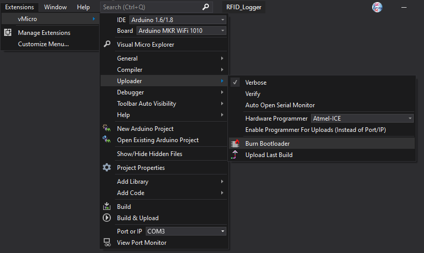
My prior blog includes all the pics on connections and such. The only thing needed is this information on how to burn the bootloader from within Visual Studio using the Visual Micro Arduino Extension. Once the Atmel ICE is connected, a fresh bootloader is just a couple of clicks away:


Menu selection for burning a fresh bootloader on the Arduino MKR Wi-Fi 1010 Board
A successful load should have an output like this:

Burning a new bootloader
Burning bootloader to board 'Arduino MKR WiFi 1010' using 'Atmel-ICE'
Erase Pattern: 
Bootloader Pattern: "{path}/{cmd}" {bootloader.verbose} -s "{path}/share/openocd/scripts/" -f "{runtime.platform.path}/variants/{build.variant}/{build.openocdscript}" -c "telnet_port disabled; init; halt; at91samd bootloader 0; program {{{runtime.platform.path}/bootloaders/{bootloader.file}}} verify reset; shutdown"
C:\Users\gojimmypi\AppData\Local\arduino15\packages\arduino\tools\openocd\0.9.0-arduino6-static\bin\openocd.exe -d2 -s "C:\Users\gojimmypi\AppData\Local\arduino15\packages\arduino\tools\openocd\0.9.0-arduino6-static/share/openocd/scripts/" -f "C:\Users\gojimmypi\AppData\Local\arduino15\packages\arduino\hardware\samd\1.6.20/variants/mkrwifi1010/openocd_scripts/arduino_zero.cfg" -c "telnet_port disabled; init; halt; at91samd bootloader 0; program {{C:\Users\gojimmypi\AppData\Local\arduino15\packages\arduino\hardware\samd\1.6.20/bootloaders/mkrwifi1010/samd21_sam_ba_arduino_mkrwifi1010.bin}} verify reset; shutdown"
Open On-Chip Debugger 0.9.0-g932ec70 (2017-02-15-12:34)
Licensed under GNU GPL v2
For bug reports, read
 http://openocd.org/doc/doxygen/bugs.html
debug_level: 2
Info : only one transport option; autoselect 'swd'
adapter speed: 500 kHz
adapter_nsrst_delay: 100
cortex_m reset_config sysresetreq
Info : CMSIS-DAP: SWD  Supported
Info : CMSIS-DAP: JTAG Supported
Info : CMSIS-DAP: Interface Initialised (SWD)
Info : CMSIS-DAP: FW Version = 01.27.0082
Info : SWCLK/TCK = 1 SWDIO/TMS = 1 TDI = 1 TDO = 1 nTRST = 0 nRESET = 1
Info : CMSIS-DAP: Interface ready
Info : clock speed 500 kHz
Info : SWD IDCODE 0x0bc11477
Info : at91samd21g18.cpu: hardware has 4 breakpoints, 2 watchpoints
target state: halted
target halted due to debug-request, current mode: Thread 
xPSR: 0x81000000 pc: 0x00004aac msp: 0x20007fa8
target state: halted
target halted due to debug-request, current mode: Thread 
xPSR: 0x81000000 pc: 0x00000b80 msp: 0x20007ffc
** Programming Started **
auto erase enabled
Info : SAMD: partitioning the first flash page into 8 subpages
Info : SAMD MCU: SAMD21G18A (256KB Flash, 32KB RAM)
wrote 8192 bytes from file C:\Users\gojimmypi\AppData\Local\arduino15\packages\arduino\hardware\samd\1.6.20/bootloaders/mkrwifi1010/samd21_sam_ba_arduino_mkrwifi1010.bin in 0.869252s (9.203 KiB/s)
** Programming Finished **
** Verify Started **
verified 7992 bytes in 0.676364s (11.539 KiB/s)
** Verified OK **
** Resetting Target **
Done burning bootloader.
Burn complete
shutdown command invoked


That's it! Once the bootloader has been installed, the MKR WiFI 1010 can once again be programmed over the serial port.

If problems are encountered while programming, try pressing the reset button on the board. Keep in mind that this causes the USB device to go away and come back. So if there's a VM Workstation running, there may be a prompt to connect the "new" device to host or virtual machine. The delay in answering that can also cause programming to fail.

Edit: If any problems are encountered seeing the device as a serial port after developing with the Atmel ICE, try loading up a blank program in release mode with the Atmel Studio and then burning the bootloader fresh:


/*Begining of Auto generated code by Atmel studio */
#include <Arduino.h>

/*End of auto generated code by Atmel studio */

//Beginning of Auto generated function prototypes by Atmel Studio
//End of Auto generated function prototypes by Atmel Studio

void setup() {
  // put your setup code here, to run once:
}

void loop() {
  // put your main code here, to run repeatedly:
  delay(1000);
}


Saturday, June 6, 2020

Programming FPGA Devices from WSL

Today I received a DM on Twitter asking for help to program an FPGA (specifically the 1bitsquared iCEBreaker) from WSL. I realized that most of the useful information is buried in my long (and admittedly sometimes rambling) prior blogs. So this is a summary for just that topic.

The first thing to do, is plug in your device. In the case of the iCEBreaker, make sure the drivers are set to libusbk using Zadig as noted here:


Note that native USB drivers are not supported in WSL (well, WSL1, anyhow; I've not been able to install WSL2 just yet)

If after changing the drivers the board is *still* not recognized by iceprog, try unplugging, waiting a few seconds and plugging the iCEBreaker back into the USB port. I've also seen mixed results with hubs, so perhaps try connecting directly if it still does not work.

Next, make sure you have the DOS version of the programmer on the Windows filesystem. I have mine in my C:\workspace\ulx3s-toolchain\bin\ directory:


The really crazy thing about WSL, is that not only is the Windows file system available in the /mnt/ directory such as /mnt/c for c:\ ... but Windows executables can be launched from the WSL prompt as well! And of course there's plenty of native USB driver support in Windows.

Here's an example in /mnt/c/users/gojimmypi/source/repos/Verilog12/Verilog12 - a WSL directory which is C:\users\gojimmypi\source\repos\Verilog12\Verilog12 (created by Visual Studio)

Calling the DOS executable to program the iCEBreaker:


That's it!

Links:


Sunday, February 16, 2020

C# on the Radiona ULX3S using the nanoFramework dotnet CLR

It has been over a year since I first learned about the Radiona ULX3S development board. This is the perfect "crossover" board that has appeal for developers interested in electronics, FPGA development, and even just regular software development. With both an Espressif ESP32 and the Lattice ECP5, along with a ton of peripherals and GPIO pins - there's something for everyone here.

Radiona ULX3S from https://radiona.org/ulx3s/
The ULX3S is coming soon to CrowdSupply!

If you just want to get started with C#, see my notes here or visit docs.nanoframework.net.

A lot has changed since I first heard the name Espressif way back in 2015 and ordered this thing called a "Diymall® Esp8266 Esp-12e Serial Wifi Wireless Transceiver Module for Arduino UNO 2560 R3 Nano" from Amazon. Ooph. What a name.


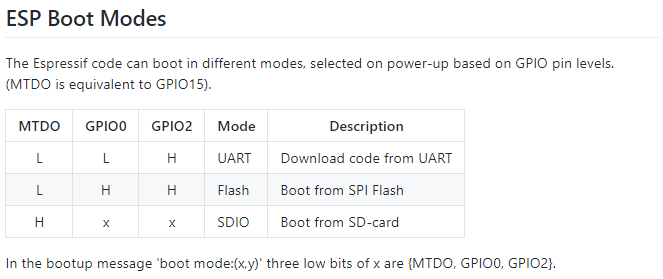
And what an ordeal it was to get that device going... I remember the convoluted process of manually holding some GPIO pin low while it powered up, and then releasing another, all with level-shifting the 5V USB-TTL on a rats-nest breadboard of jumper wires.  The "excitement' was seeing the old modem-style "AT" command prompt. Admittedly, it was pretty cool. How really surreal that was - to see the Hayes-like AT prompt for a WiFi device.

ESP Boot Modes from the ESP8266 WiKi

Indeed it seemed interesting to have modem-like commands available in such a small and inexpensive package (who knows what it would take to actually send and receive WiFi packets with AT commands!). The documentation was pretty bleak and ridiculously incomplete at the time.

Fast forward just 5 years (that's 103 in technology years) - and Espressif continues to amaze with awesome documentation and ridiculously inexpensive hardware. And the languages! I've not seen an AT prompt on any of my devices for a long time. Starting with Lua on the ESP8266, the tech community soon realized that other languages could be implemented on the Espressif hardware. Of  course, C/C++ was the first and most obvious choice for embedded devices. But then something really crazy came along: MicroPython on the inexpensive ESP8266 WiFi device. Just a few months after seeing that first AT prompt, I backed the MicroPython on the ESP8266 crowd funding project. One thing led to another and now there are many languages available, and of course the next gen ESP32 hardware platform. It was when looking at the languages on the ESP32 Wikipedia page, of all places - that I learned about a truly amazing language capability: C# on an embedded device!

I've been programming C/C++ on and off over the course of many years. At the Day Job however, my focus these days is on C# in the Visual Studio environment. That's where I am probably most comfortable and the most productive. For programming "Arduino Style" C/C++ on embedded devices, my go-to tool has been the Visual Micro add-in extension for Visual Studio. With hundreds of thousands of downloads and a solid 5 star rating, I'm clearly not alone in liking Visual Micro. I've mentioned them numerous times in prior blogs, such as this one for the ULX3S.


If you've never used the Visual Micro extension, I highly recommend giving it a try.

Back to the topic of this blog. C#. On. an. embedded. device. WOW! As mentioned above, I originally learned of this capability on the Wikipedia page. There's also a reference on the Espressif web site with a relatively simple name of "nanoFramework":

"Developers can harness the powerful and familiar Microsoft Visual Studio IDE and their .NETC# knowledge to quickly write code without having to worry about the low-level hardware intricacies of a microcontroller. Desktop .NET developers will feel “at home” and are able to use their skills in embedded systems development, enlarging the pool of qualified embedded developers. It includes a reduced version of the .NET Common Language Runtime (CLR) and features a subset of the .NET base class libraries along with the most common APIs included in the Universal Windows Platform (UWP) allowing code reuse from desktop applications, IoT Core applications, thousands of code examples and open source projects. Using Microsoft Visual Studio, a developer can deploy and debug the code directly on real hardware." --Espressif Systems
Ok, so C# on an embedded device is amazing in itself. If you've read some of my prior blogs, you've seen my interest in single-step JTAG debugging the Espressif chips. The ESP8266 in particular can be quite difficult, depending on the vendor. Still, even with JTAG working, I've never been able to get the real experience of full debugging as seen in Visual Studio with high-level language debugging, or even the Atmel Studio with the Atmel ICE for their chips.

Enter nanoFramework. This is one of the most amazing implementations I've seen in quite some time. They have the .Net CLR on an embedded device! Not just the CLR, but the fully integrated Visual Studio debugging, single-step, hover-text values and more. Getting started is pretty straightforward: first step of course is to install the nanoFramework extension from the Visual Studio Marketplace. Note there are two flavors: the nanoFramework for VS2017 and a preview nanoFramework for VS2019.

I do think their instructions are a bit overly complicated for the first time user. For one - compiling the entire framework is certainly not required to program C# on your device, yet it is featured front and center on the getting started page. I have some notes of my own on Programming the ULX3S ESP32 using C# in Visual Studio. Basically the firmware needs to be uploaded to the device, then Visual Studio needs to connect with Device Explorer.

I tweeted this video of single-step blinky in C# to show single step in action.

Beyond blinky, I was curious as to what else could be done with this framework. So how about a simple "Hello World" printed on the screen? Ha! What a twisty little passage all alike rabbit-hole that turned out to be.

First, I discovered there's currently no direct support of the SSD1331 SPI display that I am using with the ULX3S. However, there are plenty of Arduino-style libraries out there. Hm. Arduino libraries... ah yes, it is one thing to be able to write code, it is another issue altogether to actually be able to leverage the existing libraries for peripherals. All the open source code out there that allows the ESP32 to use Ardunio libraries has certainly helped the self-sustaining fire of maker interest and development. But what about C#?

I started out in the #Targets-ESP32 thread on the nanoFramework Discord. Yes, they need multiple threads for different platforms, as they also have C# working on STM32,  TI CC13x2, CC26x2, CC32xx, and NXP MIMXRT1060_EVAL boards! As my issue was not ESP32 specific, they kindly referred me to the #UI thread (UI meaning "display hardware", not the UI of the nanoFramework extension in Visual Studio). It is there that I learned a lot of great information from some clearly talented developers that very kindly and patiently answered my newbie questions.

I only recently started using Discord. I think I like gitter channels more, but both seem to be weak for linking to specific comments of interest. Part of this blog is for me to gather up the key tidbits all in one place. Be sure to check out the ULX3S gitter channel, too.

I learned quite a bit about the SSD1331 display during a exchange with emard in ULX3S issue #8. For the nanoFramework here I started with a known-working project, my ULX3S Visual Micro SSD1331 Display Example. In particular, the key pin numbers:

// working ULX3S  
#define oled_csn  17 // aka cs - chip select
#define oled_dc   16 // aka ds aka a0 -  SPI data or command selector pin
#define oled_resn 25 // aka rst - reset
#define oled_mosi 15 // aka mosi - data
#define oled_clk  14 // aka sclk - clock
#define oled_miso -1 // 12 not used

from the FPGA perspective:

N2 to N3 for oled_csn /CS  to wifi_gpio17 (GPIO17)
P1 to L1 for oled_dc /DC   to wifi_gpio16 (GPIO16)
P2 to E3 for oled_resn/RES to wifi_gpio25 (GPIO25)
P3 to J1 for oled_mosi/SDA to sd_cmd      (GPIO15)
P4 to H2 for oled_clk /SCL to sd_clk      (GPIO14)

See also this code on the espressif/arduino-esp32 repo for VSPI and HSPI initialization and pins:


void setup() {
  //initialise two instances of the SPIClass attached to VSPI and HSPI respectively
  vspi = new SPIClass(VSPI);
  hspi = new SPIClass(HSPI);
  
  //clock miso mosi ss

  //initialise vspi with default pins
  //SCLK = 18, MISO = 19, MOSI = 23, SS = 5
  vspi->begin();
  //alternatively route through GPIO pins of your choice
  //hspi->begin(0, 2, 4, 33); //SCLK, MISO, MOSI, SS
  
  //initialise hspi with default pins
  //SCLK = 14, MISO = 12, MOSI = 13, SS = 15
  hspi->begin(); 
  //alternatively route through GPIO pins
  //hspi->begin(25, 26, 27, 32); //SCLK, MISO, MOSI, SS

  //set up slave select pins as outputs as the Arduino API
  //doesn't handle automatically pulling SS low
  pinMode(5, OUTPUT); //VSPI SS
  pinMode(15, OUTPUT); //HSPI SS

}

I tried to use the existing SPI capabilities of the nanoFramework, but I was unable to get the display to cooperate. Nothing happened. But why?

This is where more serious hardware debugging tools are needed. One method I used in the past to debug some serial port communication problems - involved a Digital Storage Oscilloscope (in my case, a Rigol DS1054z). Even though that one is relatively small as oscilloscopes go, it was at my workbench and I was working at the kitchen table (and ok, the workbench needs to be cleaned up an organized). Not only inconvenient, but also perhaps not the most practical (power cord, size, etc). Although my serial decoding was an interesting exercise on the oscilloscope - what I really needed is a logic analyzer.

It was well over 5 years ago that I first started using the Saleae logic analyzer software. The cool thing here is that it is a computer-based debugging tool. Whereas the oscilloscope is an oscilloscope all on its own, complete with its own power cord and display - the Saleae is just a USB peripheral. It doesn't even have a wall-wart power supply: just a USB connection and logic probes.

Sure enough - after a ridiculously long time trying to figure out the display problem with software, the logic analyzer instead made the problem abundantly obvious: nothing was happening as the D/C (data command) pin. I was hoping that somehow the SPI driver would have just "known" how to control the bus for the display during NativeInit. Silly me. Of course not. Nope.


I opened this issue to implement more flexible SPI pin definitions, in particular something to manage that D/C pin. @AdrianSoundy responded with:
"The DC and Reset pins are not part of the SPI bus. They are specific to the displays. You have to create separate gpio pins for those functions."
Hm. Well, yes, I guess that is technically true. Still, I wanted to see if I could get my SPI  display to work in C#, so I took the advice and wrote my own DC-pin-controlling code to manage the data/control line, and let the native drivers handle the actual data transfer.

I created this nanoFramework SSD1331 example to manually bit-bang the SPI bus. As of the date of this blog, there's not a lot there. I leveraged the Adafruit SSD1331 C++ library to create my own limited C# OLED SSD1331 class library. I also created another class library project, this one an Arduino-style nanoFramework "pins" helper to allow the use of the familiar pinMode and digitalWrite functions when converting the Adafruit library to C#.

It is a bit of a mess at the moment, but it does have the capability of initializing the display and poking some pixels into place. It doesn't sound like much - but again, doing this from C# in Visual Studio is what made it really quite cool. I had this little victory tweet at the end of that weekend:


Drawing a line is one thing... drawing it quickly, well that's another. After the excitement had warn off (ok, it was just a blue line)... I realized just how slowly the pixels were being drawn. Why? Did I mention the little twisty passages? Yes, this rabbit hole goes much deeper.

To start, let's go back to the known-working SPI display example. See also this blog where I go into more detail with that example.

Again, there's nothing like a logic analyzer to see what's going on with the voltage levels of ones and zeros on the wires. Looking at the source code, the SPI bus for the display gets interesting at startup time, or specifically during Adafruit_SSD1331::begin - where initialization bytes are sent to the display:


void Adafruit_SSD1331::begin(uint32_t freq) {
    initSPI(freq, SPI_MODE0);

    // Initialization Sequence
    sendCommand(SSD1331_CMD_DISPLAYOFF);   // 0xAE
    sendCommand(SSD1331_CMD_SETREMAP);          // 0xA0
#if defined SSD1331_COLORORDER_RGB
    sendCommand(0x72);    // RGB Color
#else
    sendCommand(0x76);    // BGR Color
#endif
    sendCommand(SSD1331_CMD_STARTLINE);  // 0xA1
    sendCommand(0x0);
    sendCommand(SSD1331_CMD_DISPLAYOFFSET);  // 0xA2
    sendCommand(0x0);
    sendCommand(SSD1331_CMD_NORMALDISPLAY);   // 0xA4
    sendCommand(SSD1331_CMD_SETMULTIPLEX);  // 0xA8
    sendCommand(0x3F);     // 0x3F 1/64 duty
    sendCommand(SSD1331_CMD_SETMASTER);   // 0xAD
    sendCommand(0x8E);
    sendCommand(SSD1331_CMD_POWERMODE);   // 0xB0
    sendCommand(0x0B);
    sendCommand(SSD1331_CMD_PRECHARGE);   // 0xB1

...etc


This is where I had a chance to try out my new Saleae logic analyzer. It's funny how once you buy something, you start noticing other people that have that same "thing". I noticed that @GregDavill had posted something on Twitter with his Saleae - and so I commented on it. His reply was crazy! I don't think I'll be using mine as a coaster anytime soon LOL. So here's my new Saleae, sans mug, hooked up to my Radiona ULX3S:

ULX3S with SSD1331 display on a breadboard with Saleae Logic Analyzer
In order to most easily connect the logic analyzer, I disconnected the display from the main ULX3S board and plugged it into the breadboard. Here, I would have preferred that the Saleae had male connector pins instead of female, but a few short M-M jumpers to the rescue.

I did buy my own Dupont crimping too la few years back, so I will probably make my own Saleae male-pin probe set for breadboards. The only think needed is some wire and a Dupont header kit such as this one on ebay.

So back to the setup: Not completely intuitive is the trigger and decoding of the SPI signals. The first thing is to setup the start of capture based on the falling edge of the clock:


The next is to tell the Saleae software *which* pins are being used for decoding. First select the SPI decoder on the right side of the app:


Next, click on the little gear and "edit settings" to select which channels are which SPI pins:


The good thing is that if you don't need to change protocols, the software remembers this even after uninstalling and re-installing new software. So until you change debugging projects, the setup of the logic analyzer stays consistent.

From a software perspective, we just simply expect the bytes to be sent. But to actually see what's going on, the logic analyzer is indispensable:


Here we can see the same hex codes in the Salaea decoded from the logic analyzer probes as seen in the code segment, above. Setup of the decoder in the software was also vastly easier than the serial decoder mentioned above on my oscilloscope. The first byte sent on the SPI bus is 0xAE, the command turn turn the display off during initialization. How cool is that?

Although the Salaea software is not implemented with the proper Windows UI (banner toolbar across the top, File-Save, Help-About, etc)... for the most part it is quite easy to use and intuitive. One of the less-obvious features is that you can double click on the decoded values in the lower right, and the display auto-scrolls and auto-scales to the trace for that value. Very nice.

Once I had a benchmark of sending a byte of SPI data in under 8 micro-seconds, let's see what happens when manually bit-banging the pins from C#. Here's the code to send an SPI byte:


        private void spiWrite(byte b)
        {
            for (byte bit = 0; bit < 8; bit++)
            {
                if ((b & 0x80) > 0)
                {
                    SPI_MOSI_HIGH();
                }
                else
                {
                    SPI_MOSI_LOW();
                }
                SPI_SCK_HIGH();
                b <<= 1;
                SPI_SCK_LOW();
            }
        }


This is pretty straightforward and almost identical to the Adafruit C/C++ code in their SPITFT library (minus the hardware-specific conditional compile directives) that I based my C# code on. See also the spiWrite() in esp32-hal-spi.c.

Next, I tried to use the built-in nanoFramework SPI driver, but manually control the D/C line.


private void WriteCommand(byte command)
        {
            _buffer1[0] = command;

            // the time between the next two statements is a whopping 0.3ms
            _DS.Write(GpioPinValue.Low);
            _DS.Write(GpioPinValue.High);

            // here we manually bring DS low
            _DS.Write(GpioPinValue.Low);
            _spi.Write(_buffer1); // all 8 bits in about 54uS
            _DS.Write(GpioPinValue.High);
        }


Here's what it looks like on the logic analyzer:


Notice in particular the vastly longer delay in switching the D/C line as compared to the bits sent during the native _spi.Write(). There's nearly three-quarters of a millisecond window for the D/C line, but only about 54 microseconds to send the entire 8 bits of data:


When I posted this information on the Discord channel, @terryfogg suggested that I review a similar example being worked on. From what I could tell, it was VSPI with a different set of pins and also confirmed that C# is just too slow for this kind of, so instead this was using native code. Ah yes, the twisty little passage - the Rabbit hole goes on to another whole level: calling native code from C# on an embedded device.

The next level of complexity? Interop of course. To get started, there's a pretty good tutorial on Interop in the .Net nanoFramework. Yes, interop of course pretty much screws the entire concept of managed code, but with the benefit of vastly better performance. Hm. See the links at the bottom of this page for more information on calling unmanaged code from C#. I think that's probably a whole topic in and of itself. Stay tuned...


Full disclosure: I purchased the Saleae Logic Pro 16 at a substantial discount since I (sadly) don't do this fun stuff for a living. Saleae has a "Electronics Enthusiasts (non-commercial use)" discount. My primary motivation was the USB3 sampling speeds of up to 125MHz to be used as I dig deeper into the ULX3S FPGA capabilities. The discount of course made all the difference for my hobbyist budget. In fact, there's an "Enthusiast Discount Extreme Edition" that I hope to qualify for with this blog entry.

I purchased the ULX3S early last year from Goran after reading about it on Hackaday and sending an email. Although I am listed as one of the members of the Radiona CrowdSupply team, I am not employed by Radiona, nor do I receive any financial compensation from them.

All opinions expressed here are my own and not representative of my employer.


Resources, Inspiration, Credits, and Other Links:
Saturday, June 1, 2019

ULX3S and Visual Micro in Visual Studio 2019

This blog is a walk-though using the Visual Micro Arduino IDE in Visual Studio 2019 to program the ESP32 on the Radiona ULX3S. For more information on the ULX3S see my Day 1 intro, Using ujprog on WSL or MinGW, and Notes on ulx3s FPGA: Yosys, Verilog, VHDL, vhdl2vl (Convert VHDL to Verilog). Here's the ULX3S with the SPIDriver.

ULX3S with SPIDriver board
There are some brief online instructions for manually installing Visual Micro, or you can follow along here, using the VisualMicro example for the ULX3Son GitHub:

In Visual Studio 2019, click on Extensions - Manage Extensions.


Select "online" in the left pane and type "Arduino" in the search box:


Note the 5 stars reviews from hundreds of users. Yes, it is a very cool extension. :)

Next, click on the "Download" button. You'll need to restart Visual Studio 2019.

Be sure to wait for the VSIX installer screen! The first time I did this, I simply launched Visual Studio right away, and the Visual Micro Extension was no where to be found! Before launching Visual Studio, you should see this screen:


Then after a warning about system changes, this prompt:


Click the "Modify" button to continue. Upon completion, there should be a message "Modifications Complete"


When Visual Studio is next launched, click on "Create a new project"


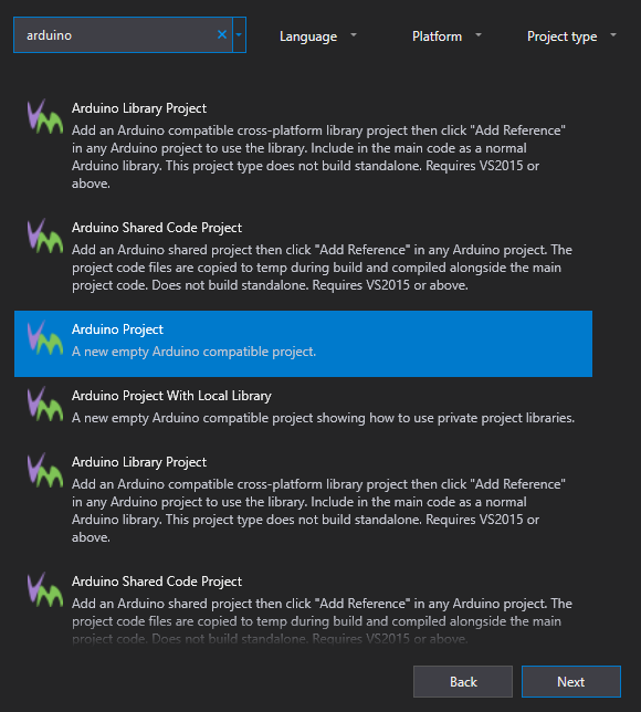
There are many project types, so type "Arduino" in the search box:


Select "Arduino Project" and click the Next button.


Give the project a name, and a location to store it. In this case, I am saving it in my ULX3S examples fork directory, to create a pull request to the official ULX3S Examples.

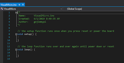
After clicking  the "Create" button, a familiar Arduino-style code template is created, with the setup() and loop() functions:


So that's the easy part. Now things get more interesting. The ESP32 on the ULX3S sits behind the FPGA chip. This means the only way to program the ESP32, is to have code on the ULX3S that performs a "pass through" function of external physical pins to the ESP32 pins through the FPGA.

schematic showing the ESP32 to FPGA connections


Fortunately, the ULX3S typically ships with the pass-though FPGA app already loaded. If not, the FPGA source code can be found here. Note there are three different versions: the Diamond VHDL that emard wrote, a Diamond Verilog that I converted from emard's VHDL, and finally an Open Source Verilog version that uses yosys and nextpnr. (hm, it looks like from the most recent comments I need to get the open source version working properly - I'll need to look into that)

If you are not ready to jump into the synthesis of FPGA bit files yet, you can use the passthru image file passthru_ulx3s_v20_12k.bit and load it onto the ESP32 using the ujprog tool. If you don't feel like building your own, there's a copy of both the bin directory.


if NOT EXIST c:\workspace mkdir c:\workspace
git clone https://github.com/gojimmypi/ulx3s-examples.git c:\workspace\ulx3s-examples
c:
cd \workspace\ulx3s-examples\VisualMicro\bin\
.\ujprog.exe passthru.bit


If "Cannot find JTAG cable" is encountered, remember that WSL is still not supporting native USB drivers. If you are using the Windows executable version and you see that message try changing the ULX3S drivers back to FTDI particularly if you don't see your ULX3S in the Ports (COM & LPT) container in device manager. WSL can be finicky, and even have different results whether executing from a Linux directory or DOS (e.g. /mnt/c/). And yes, native Windows executable files can be launched from WSL! cool.

Visual Studio seemed to have defaulted to all the correct values for me (I'm note sure if perhaps it remembered values from Visual Studio 2017) Here they are for reference:


Of particular interest is ensuring the proper COM port is selected, near the bottom of the settings list. I didn't see the actual ESP32 device listed (WROOM-32), so I used the ESP32 Dev Module setting.

Once the pass through FPGA binary has been successfully uploaded, the simplest way to compile and upload the Arduino code via Visual Micro is to press F5 or the big green "start" button! That's it!

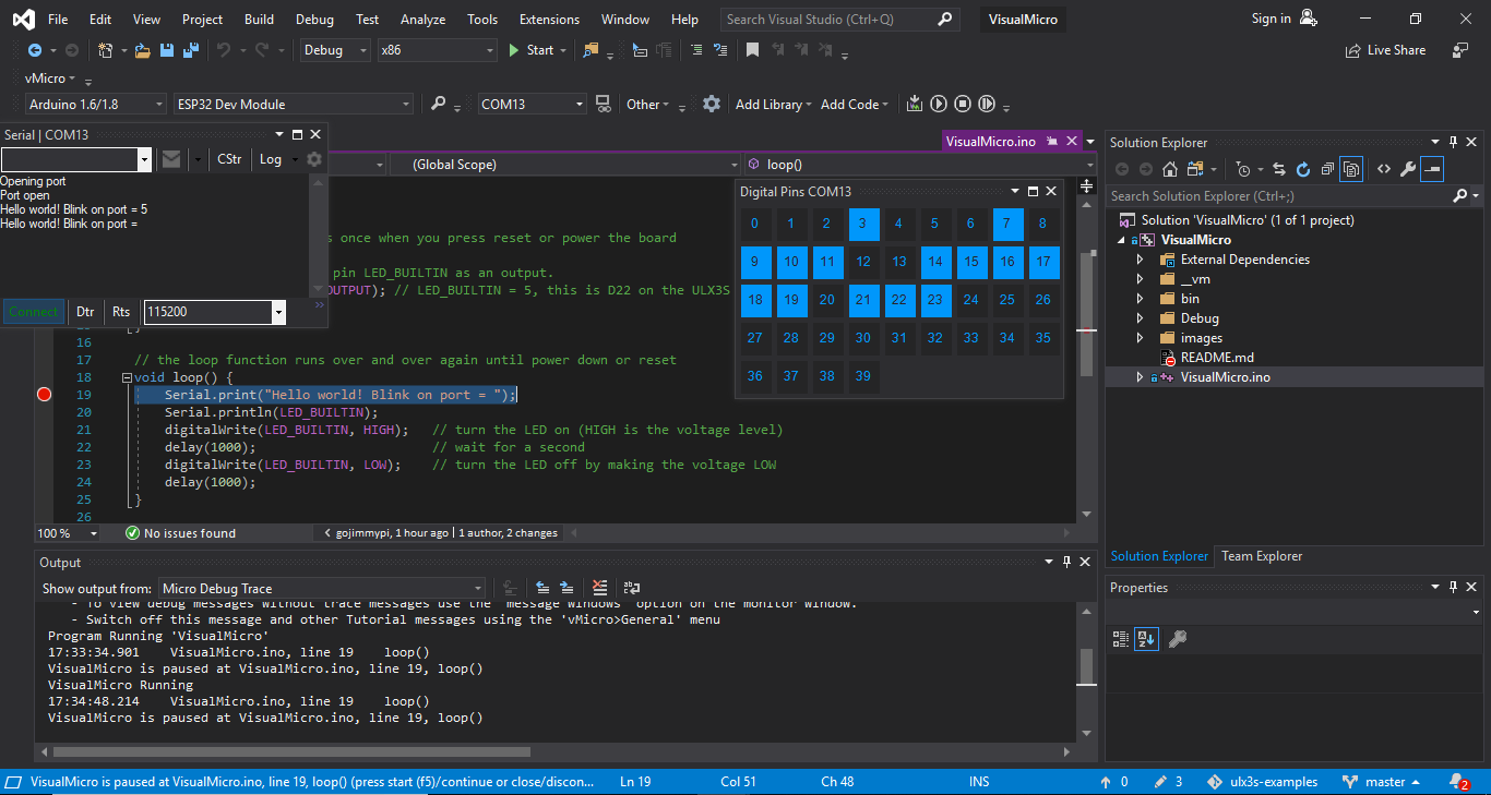
Note that one of the amazing things about the Visual Micro IDE, is they have implemented a debugger that does not require a hardware JTAG device! Here's my ULX3S ESP32 paused at a breakpoint:


Now onto that SPI Driver! Stay tuned for more....


Tuesday, March 13, 2018

The Magic of Visual Studio and GitHub Integration

The more I use Visual Studio 2017 and the integration with GitHub, the more I am amazed at just how well this all works. I'll use a real-world walk-through with some Espressif ESP32 Arduino code that I am using on my M5Stack to show how really useful this is.

First, note that I have a couple of add-ins installed (Tools - Extensions and Updates). In particular the Arduino IDE for Visual Studio and the GitHub Extension for Visual Studio.


I was reading this thingpulse blog entry on reducing ESP32 power when I noticed the line:
WiFi.forceSleepBegin();

Hmm... interesting. But when I tried to use that, it seems to not be implemented for me:


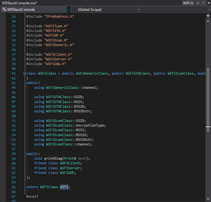
So here we can right click on WiFi and Go To Definition:


And sure enough.. the WiFi.h file opens... but as a "soft" open tab on the right, instead of the regular solution file on the left; hmm. there's no forceSleepBegin() in the header. Let's see if we can find out more.


It gets more interesting, as now we can right click on the WiFi.h tab name and select Open Containing Folder:


So here I can see which of the several (in my case Arduino or ESP32) WiFi libraries are actually being used in this project. In the path we see the ESP32 library is being referenced:


Now.. this directory was installed via a git clone command some months ago.

Even more cool, is we can right-click on Windows Explorer and Open in Visual Studio. (yes, going back!) Be sure to click on white page in the Explorer file list, and not on a specific file. Otherwise only that single file will be opened.


Note how the ~\src directory is opened in the solution. Looking closely, there are little lock symbols next to each file! I didn't do anything to set that up. It just works!


Yes, those little locks say "this is a file under source control and has not been checked out nor edited".

Next, to really see the magic, click on the Team Explorer tab (or View - Team Explorer).


Look! A Welcome to GitHub for Visual Studio message. It just knows that this subdirectory has a parent directory somewhere above that has the git clone repository information. How cool is that!?!

Click on the Sync Button/Tab and we can see the incoming commits, LIVE from GitHub!

Here we can press the Fetch link to just bring in the historical information, but not change our local files.


Want something else? Click on the master Branch text/link, to view the other branches:


Double-click to select a different branch. All the usual git commands apply, so git stash is probably your friend here. (unfortunately manually from command line, as far as I know)

Sadly, the "Search Work Items" does not seem to work for me; I cannot type anything there. That will soon be a Very Cool feature.

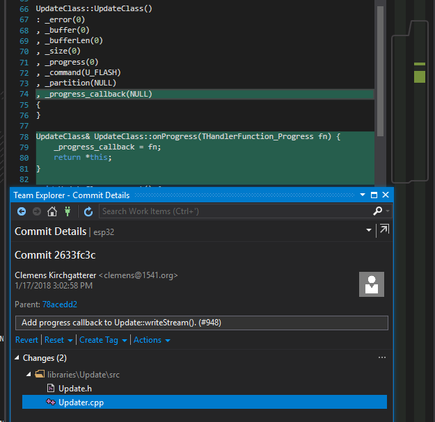
We can however, right-click on commit items and compare & see what changes by pulling each commit:


All from the comfort of the Visual Studio UI. How really awesome is that!?! :)

Close the yellow welcome message banner and we can see exactly where this repository lives on GitHub. Press the little home icon any time in Team Explorer to return to this view:


Click on the repository link and the GitHub web page for the repository (in this case Espressif Aduino repository on GitHub) opens in your default browser.

As a suggestion, there are probably some files that should be added to your .gitignore file. Simply going though this exercise creates some files that you probably don't want to push back to the repository and may interfere with pulls. Click the Changes tab/button on the Team Explorer home to see what's been added:


These will of course interfere with selecting other branches, etc.

Overall this is really quite cool. The developers creating Visual Studio simply rock. :)

There's a ton of other cool stuff going on. Be sure to check out The Visual Studio Blog and the Visual Studio conversation in the Gitter community.


Other links:

Sunday, March 4, 2018

M5Stack LoRa Range Improvement


Last month I started working on a project to control GPIO pins on a device (relatively) very far away using LoRa technology. Most of the showstopper problems seem to have been resolved. Well, at least getting the RadioHead code working on the M5Stack. This blog entry continues on that topic...

TL;DR
  • VisualMicro Arduino projects in Visual Studio, using 32u4 (see also Adafruit 32u4) and M5Stack - both over LoRa.
  • M5Stack RSSI is a solid RSSI strength of 10 points worse than the exact same code on 32u4 which has the exact same RA-02 AI-Thinker LoRa device.
  • Recall from previous blog, LoRa RST and IRQ are reversed. (RST is actually GPIO36 input only; unusable). Otherwise it would have been: Beep = LoRa reset. 
  • M5Stack Speaker (GPIO25) is shared with LoRa Interrupt. (beep = interrupt?)
  • The M5Stack display shares the NSS pin with the LoRa module. (poke registers with care!)
  • The receiver and transmitter need to be configured EXACTLY the same for best range (more than just the same frequency); but this was not the problem with our poor RSSI
  • My LoRa-GPIO project and required RadioHead and M5Stack libraries merged to master on GitHub
  • When updating library (include) code, Visual Studio apparently does not look at file dates and may use previous compiled code; clean project after library changes.
The latest working (although not very pretty) Very Remote Lora-GPIO Control and Monitoring Project code has been merged onto my master branch.

I've merged my M5Stack development branch back to my RadioHead master branch. This was a "Squash and Merge". Normally I like to keep the history... but as the RadioHead owners prefer a single patch file, perhaps this will be better. Time will tell. History is still in the branch.

I've submitted a PR to Adafruit at their request, as well as well as sent a patch file to Mike at ReadioHead. Ok, this is weekend and evening working, certainly not some of my best polished work. I need to go back and clean things up.

My M5Stack library fork is, and has been up to date on the master branch. (no branches)

The main LoRa-GPIO solution contains several projects as noted in the GitHub readme. These are all Arduino-style projects using the really awesome VisualMicro add-in for Visual Studio.

As a side note, while working on this - I found what appears to be GitHub branch-to-branch compares not working properly.  (if it *does* work properly and I'm simply not doing it correctly, please let me know)

I've been reading through the ARRL Ham Radio License manual. I don't know if I will actually get a ham license, but wow - what a great book this is to cover the essentials of what you need to know for RF communications (such as the LoRa for this project). Although I had a ton of classes in college covering a wide variety of electronics, electromagnetism, communications, even an entire class on antenna theory... this ARRL book contains a lot of relatively straightforward, every-day language on the practical essentials of radio frequency communication - all in one place. The ARRL web site also has some excellent resources. Ok, there's also pretty much NO math, NO theory: Just useful facts. So this is certainly not a book for how or why or how to apply to new problem. Still, it is a quite good book. Highly recommended & would make a great gift for someone new to the field.

So on to the testing... now that I have the RadioHead drivers working, I actually went back to the M5Stack example code (Sandeep drivers renamed M5LoRa). Recall that I have the RadioHead drivers on a remote 32u4 sending LoRa packets. Here's the sample code for the M5Stack receiver (Arduino: File - Examples - M5Stack - Modules - LoRa - LoRaReceiver) :


#include 
#include 

#define LORA_CS_PIN   5
#define LORA_RST_PIN  26
#define LORA_IRQ_PIN  36

void setup() {
  
  M5.begin();

  // override the default CS, reset, and IRQ pins (optional)
  LoRa.setPins(LORA_CS_PIN, LORA_RST_PIN, LORA_IRQ_PIN); // set CS, reset, IRQ pin
  Serial.println("LoRa Receiver");
  M5.Lcd.println("LoRa Receiver");

  // frequency in Hz (433E6, 866E6, 915E6)
  if (!LoRa.begin(433E6)) {
    Serial.println("Starting LoRa failed!");
    M5.Lcd.println("Starting LoRa failed!");
    while (1);
  }

  // LoRa.setSyncWord(0x69);
  Serial.println("LoRa init succeeded.");
  M5.Lcd.println("LoRa init succeeded.");
}

void loop() {
  // try to parse packet
  int packetSize = LoRa.parsePacket();
  if (packetSize) {
    // received a packet
    Serial.print("Received packet: \"");
    M5.Lcd.print("Received packet: \"");

    // read packet
    while (LoRa.available()) {
      char ch = (char)LoRa.read();
      Serial.print(ch);
      M5.Lcd.print(ch);
    }

    // print RSSI of packet
    Serial.print("\" with RSSI ");
    Serial.println(LoRa.packetRssi());
    M5.Lcd.print("\" with RSSI ");
    M5.Lcd.println(LoRa.packetRssi());
  }
}

This code writes to  both the M5Stack display as well as the serial port. The display is cool as I don't need to remember to disconnect the serial port when reprogramming. HOWEVER: You may recall from my previous blog that the M5Stack display *and* LoRa module share the NSS (slave select) pin. That simply sounds dangerous (and indeed I observed some display oddities), so I put M5Stack LoRa to sleep when writing to the display.

The shocking thing here is that there's up to a difference of TEN in RSSI values as compared to using the RadioHead drivers. (RSSI 36 vs 26). As this is a log scale, that's a 10x difference in power! Now - this is not to say that the Sandeep library has a problem just because it is polling rather than using interrupts. It is a matter of default configuration. I picked apart the RadioHead control register libraries and added a note about the matching importance:


When printing the register values from the Sandeep (M5LoRa) library, (move the readRegister from the private to public section)...

    Serial.print("0x");
    Serial.print(LoRa.readRegister((uint8_t )0x1d),HEX);
    Serial.print(", 0x");
    Serial.print(LoRa.readRegister((uint8_t )0x1e),HEX);
    Serial.print(", 0x");
    Serial.print(LoRa.readRegister((uint8_t )0x26),HEX);


There's a SINGLE BIT different (CRC not enabled!):  0x72, 0x70, 0x4 - alas that didn't seem to make much of a substantial difference in RSSI values. I supposed I had expected different error coding, spreading factor, or some other obvious difference.

I confirmed the running values of RadioHead cinfig registers are also 0x72, 0x70, 0x4 - but the RSSI is typically -25 whereas the Sandeep (M5Lora) drivers report an RSSI of typically -35!

So the next thing is: how to each of them calculate RSSI?


Well, the Sandeep / M5Lora library does this:

int LoRaClass::packetRssi()
{
  return (readRegister(REG_PKT_RSSI_VALUE) - (_frequency < 868E6 ? 164 : 157));
}

float LoRaClass::packetSnr()
{
  return ((int8_t)readRegister(REG_PKT_SNR_VALUE)) * 0.25;
}

But the RadioHead library does this:
// Remember the last signal to noise ratio, LORA mode
// Per page 111, SX1276/77/78/79 datasheet
_lastSNR = (int8_t)spiRead(RH_RF95_REG_19_PKT_SNR_VALUE) / 4;

// Remember the RSSI of this packet, LORA mode
// this is according to the doc, but is it really correct?
// weakest receiveable signals are reported RSSI at about -66
_lastRssi = spiRead(RH_RF95_REG_1A_PKT_RSSI_VALUE);
// Adjust the RSSI, datasheet page 87
if (_lastSNR < 0)
 _lastRssi = _lastRssi + _lastSNR;
else
 _lastRssi = (int)_lastRssi * 16 / 15;
if (_usingHFport)
 _lastRssi -= 157;
else
 _lastRssi -= 164;


Grr... So ok, the difference in RSSI appears to be simply a different calculation.  The real test is: how far away can the units be and still communicate? I'm still happy I have the RadioHead libraries working. In my opinion is is clearly the superior code.

So reference check: after all the code changes, let's try same units: 32u4 to 32u4. Cleaned project, full rebuild. RSSI value is -19 or -20! Rechecking the M5Stack, RSSI is -27.  So even with the same codebase and same calcs, the M5Stack LoRa has a poorer RSSI value. Using an external battery power source and the value improves to RSSI = -24.

So, as mentioned about - I've been reading about real world antennas, so perhaps the M5Stack antenna has an issue. Well, I tried that as well, replacing the internal antenna with one of those external antennas - identical to the one on the 32u4. Still there's a discrepancy in RSSI values between the two devices.

What else? Ok, so there's a speaker in the M5Stack. Poking around with that, defined in:

libraries\M5Stack\src\utility\Config.h

there's a declaration:

// BEEP PIN
#define SPEAKER_PIN 25

Ah yes, GPIO25, our friend. The LoRa interrupt pin.  (sigh)

So perhaps all the extras in the M5Stack are indeed causing a problem. I tried to disable a few things  such as the speaker init, but no luck. I do however, have another Console (without display) app that is specifically targeted for the 32u4, but with the magic of simply changing platforms in the IDE, can be recompiled and sent to the M5Stack!  RSSI about that same at -27 (ranging from -23 to -29).  Replace with the exact same code on the 32u4 and the RSSI is a full 10 points better at -17.  (10x improvement in signal strength!).

I tried another M5Stack unit with a different LoRa module. Same result.

So at this point, I really believe it is a hardware issue. I've been unable to get a copy of the schematic for the M5Stack LoRa module, However the 32u4 has a pin connection diagram here.

As soon as hardware is questioned - the first thing to do is of course add some capacitors! I added a 10uF and a 10pf cap directly to the power input to the RA-02.


In the pic, you can see I fished a new, external antenna along with the new caps. And ya, I got a little close to the side of the M5 Lora module.

Additionally I added a shield (aluminum foil sandwiched between two layers of clear packing tape) to both sides of the LoRa module. After all - there is an ESP32 microprocessor buzzing away just on the other side of the PCB!


The first field test was a relative success! I more than doubled the original range! Ok, so I didn't actually test after each change, so I don't know exactly which was the most effective in extending the range.

Note the Semtech site has a bunch of LoRa resources, including this cool LoRa calculator (I will include in my GitHub repository in the docs container, in case the link to Semtech ever breaks.


Note that I am currently transmitting at 125kHz. Lowering this increases range! Lower this to about 15.6kHz and you get another 10db in "link performance". (in theory).

Overall I am quite happy with the result. Ok, I'm not seeing multi-kilometer ranges. But that's also line-of-sight. My transmitter is on the kitchen table - with the entire garage between it and the M5Stack receiver. Next test will be from line of site.

The super exciting thing is I have a prototype from the kind folks at M5Stack arriving in the mail soon for the next potential version of the LoRa module. I am quite interested in seeing how well it performs.

Stay tuned for my next blog where I work on the prototype V2 LoRa modules with its own embedded ATMEGA328.


Resources, Inspiration, Credits, and Other Links:


Find gojimmypi at gojimmypi.github.io

I'm currently working on my new blog home at  gojimmypi.github.io After implementing a variety of features such as dark mode , syntax hi...