This is a continuation of my prior blog: The road to CNC3018 Limit Switches.
Update: I've migrated my blog to GitHub pages, here and posted the STL files here.
These parts that I custom designed are for the CNC3018 (specifically the CNC3-3018Pro) Desktop CNC Engraving Router such as the one I purchased from Twowin Tools on AliExpress. Some of these mounts may be applicable to other CNC Routers as well. ymmv.
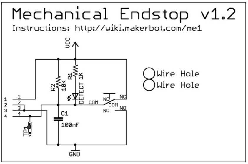
All of the designs here are for the relatively common Makerbot limit switch available on Amazon, eBay, AliExpress, etc...
There are certainly less complex implementations of limit switches.
WARNING: CNC Machining, even on a small desktop unit is inherently DANGEROUS.
I'm a software engineer at the Day Job, with relatively minimal mechanical engineering experience. This project is also my first experience with Fusion360. Although I've gone through (an embarrassingly large number of) iterations trying to take into account a surprising number of factors - there are probably still problems. DO NOT RELY ON THESE MOUNTS FOR PERSONAL SAFETY. There is no guarantee of proper operation or reliability.
WEAR EYE PROTECTION AT ALL TIMES.
For installation, I wanted to minimize any additional machine tooling: no drilling, cutting, or other modifications are needed to mount these switches.
Parts Needed:
- 6x Switches: a pair for each axis end limit: X, Y, Z.
Optional:
- Assembly tools such as a quite handy 2.5 MM Ball-Hex (allen) driver. The ball-end is just too cool for screwing in M3 nuts from an angle.
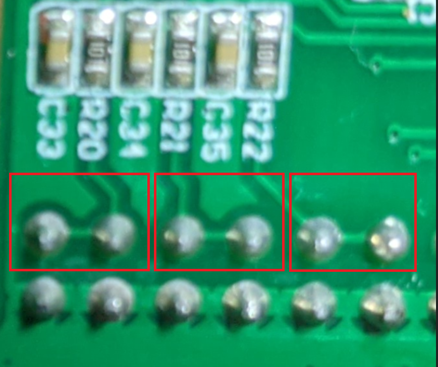
- Opto-isolator, such as the CNC Optical Limit Switch Isolator - GRBL on Tindie. Note that TWO of these boards may be needed to cover both end limits for some machines. This is clearly illustrated in the schematic that I should have studied more closely (but who would want a limit in only one direction?). As it turns out, I was "lucky" in that both ends of each axis are tied together on the PCB anyhow. So one board should work just fine for my desktop CNC:
Axis Designation
The notation in Fusion360 XYZ, Red Green Blue is followed:
X-Axis (red)
The X-Axis on the CNC3018 is the left-right worm gear holding the engraver motor. Thus the motor moves in the X and Z directions.
My final design for the X-Axis end-stops uses the black Bakelite sides as the stop for the actuator.
The switches are mounted on a pair of symmetric clip-on brackets. One is as shown:
- The wrap-around clip that holds the bracket in place.
- Holes for 5.5mm nuts. The fit is a bit tight to make assembly easier. It may be useful to first thread a screw to pull the nut into the hole.
- Wire routing channel.
- Alignment holes for the "chimney" portion of the wire routing channel extension.
- Continued wire routing channel.
- Cutout for wire exit.
- Nubs to snap into pre-existing hold in the side of the motor mount.
Here's the as-seen, design view of one of the mounting clips with the chimney:
With an additional X-Axis Clip-on Bracket, the actual assembly looks like this:
Y-Axis (green)
The Y-Axis end-stops are located underneath the plan of the the moving table. Two assemblies are used: one on each side of the router table. The design is such that the switch is positioned underneath the table to minimize debris dropping into what could have otherwise been considered a bucket in earlier designs. This was one of the many things not considered during design, but abundantly obvious once viewed in place.
There are a total 7 parts for each of the Y-Axis mounts. Although one could certainly buy mounting hardware, 4 of the printed parts are the pair of nuts and bolts:
Printing nuts and bolts is a learning opportunity (including paying attention to left or right-hand threading). The fit is not super great as-printed. I used this as an excuse to buy a metric tap and die set. These specific ones are designed as M8X1.25
Other than the 4 parts for nuts and bolts, the remaining 3 parts for the Y-Axis are the actual switch mount, lid and limit stop. The stop is a vertical thin tab designed to be break-away in case of mishap, instead of destroying the bracket housing the Y-Axis electronics:
The vertical tab stop is not only thin, but it is also printed parallel to the print bed, making it even more weak. It should only be strong enough to trigger the switch.
The body of the Y-Axis switch mount Body is considerably more complex:
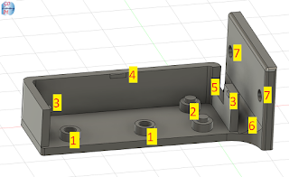
- Through-holes for mounting the PCB for the switch.
(2x) 10mm M3 screw and (2x) 5.5mm nuts.
- Posts with a snap-in nub for the other 2 holes in the switch PCB.
- Bumps to help catch and hold the lid from the sides.
- Another bump to hold the lid in place.
- Opening for wire exit.
- Narrow channel for wire routing.
- Mounting holes to mount to side rail.
(2x) 8mm M3 screw and (2x) T-Slot nuts.
The final part of the Y-Axis end-stop is the Lid:
- Catch for the bumps on the base, (#3) above.
s - Rear catch for #4 bump from above.
- Wire hold-downs.
- Window for switch trigger arm.
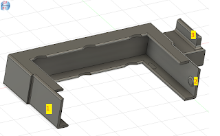
The complete, rendered Y-Axis mount Body and Lid:
A complete set of the above Y-Axis parts is used both on the left and right sides for min / max limits.
(TODO: which is which?)
It's probably best to mount the PCB inside the switch housing and install the lid before mounting to the side rail with (2x) 8mm M3 screw and (2x) 5.5mm nuts.
Z-Axis (blue)
There are 4 main components for the Z-Axis: an upper and lower end limit clip, and a 2-part switch mount. All attach to the motor mount with snap-on, press-fit.
The first part is this lower limit clip:
- The sides extend back fairly far. They are thin here to minimize any wasted travel distance range in the X direction (the motor mount otherwise travels right up flush with the Bakelite sides.
- Little round nubs catch in pre-existing holes on the motor mount.
- An extension is providing to distance the clip from the actual switch lever.
The next part is the upper clip used for the vertical limit:
Mounting brackets to snap onto the vertical Z-Axis motor spacers.
- Spare cutting bit holder. (beware the bits are extremely sharp: the protective cover for them typically protects the bit, not your fingers. Yes, I learned this the hard way. Twice. The first time, I didn't even know how I cut my finger!) TODO: design a cover.
- Not visible in this photo is a little bump that hits the upper Z-Axis switch.
Switches are mounted with this two part assembly. The first part snaps onto the motor mount:
- Mounting Holes to attach the second part that has switches mounted. (see below)
- Clearance for the upper clip.
- Clearance for the lower clip.
- Upper nub to latch housing onto motor mount.
- Part of housing "wraps around" front of motor mount here.
- Unnecessary material removed.
Posts with a snap-in nub for the other 2 holes in the switch PCB. (upper limit)
Posts with a snap-in nub for the other 2 holes in the switch PCB.(lower limit)
Through-holes for mounting the PCB for the switch. Aligns with holes in first part, the inner housing described above. This is for the lower limit switch.
(2x) 10mm M3 screw and (2x) 5.5mm nuts.
Through-holes for mounting the PCB for the switch. Aligns with holes in first part, the inner housing described above. This is for the upper limit switch.
(2x) 10mm M3 screw and (2x) 5.5mm nuts.
Unnecessary material removed.
Ridge to hold snap-on cover (TODO: design Z-Axis switch cover)
Both Z-Housing Mounts, rendered together as a single assembly:
And so I guess in the end, yes: this is a rather overly complex design for something as (seemingly) simple as CNC limit switches. Alas this is 2020 and I have plenty of time at home to learn all these things that I've wanted for so long. For a software guy like me - it is really quite amazing to draw something and have it actually end up as a physical thing, all from the comfort of my home.
If you've read along this far (hey! thank you, I'm glad someone is interested) ... and if you have a CNC machine like the one described above but do not have a 3D printer, I have a bunch of initial prototype parts that with a bit of TLC (read: they don't fully work; time needed to sand, cut, or otherwise modify and adjust) ... that could probably be adapted to function. I'm willing to ship them anywhere in the USA for free, and perhaps anywhere in the world, depending on actual destination and cost. It's a shame to throw them away and I don't know what I would do with them otherwise. So if the prototypes can go to a good home, let me know. My blog name at gmail works.
See my next blog post on
CNC 3018 Makerbot Limit Switch Wiring.
As always: I am not specifically recommending or endorsing any of the product links in this blog. None are ads, or "affiliate" links. These links are included from my personal experience, "notes to self" and for reader convenience only. If you, too, are ridiculously tired of excessive ads, check out The pi-hole.


