Showing posts with label Woodpecker. Show all posts

Monday, October 12, 2020

CNC3018 Woodpecker Grbl Firmware Notes


The Woodpecker boards shares the USB 5VDC line with the power input. I use a non-powered USB hub between my computer and the CNC machine. Honestly I'm not sure if it actually does anything to isolate or perhaps I'm just lucky. (probably the latter) TODO: find and buy a good isolated USB, such as the Adafruit USB Isolator - 100mA Isolated Low/Full Speed USB.

For reference, my current firmware version is Grbl 1.1f, or more specifically $I result:

[VER:1.1f.20170801:]
[OPT:V,15,128]

The Woodpecker board has a CH340 serial chip and is accessible via the usual putty 8N1/115200:

"Help" $$ is simply this one line:

[HLP:$$ $# $G $I $N $x=val $Nx=line $J=line $SLP $C $X $H ~ ! ? ctrl-x]

That's not very helpful, but according to the documentation, newer versions will apparently provide more details:

$$ (view Grbl settings)
$# (view # parameters)
$G (view parser state)
$I (view build info)
$N (view startup blocks)
$x=value (save Grbl setting)
$Nx=line (save startup block)
$C (check gcode mode)
$X (kill alarm lock)
$H (run homing cycle)
~ (cycle start)
! (feed hold)
? (current status)
ctrl-x (reset Grbl)

My settings via $$ (always a good idea to save these BEFORE upgrading firmware):

$0=10                                                           
$1=25
$2=0
$3=5
$4=0
$5=0
$6=0
$10=1
$11=0.010
$12=0.002
$13=0
$20=0
$21=0
$22=0
$23=0
$24=25.000
$25=500.000
$26=250
$27=1.000
$30=1000
$31=0
$32=0
$100=800.000
$101=800.000
$102=800.000
$110=800.000
$111=800.000
$112=600.000
$120=10.000
$121=10.000
$122=10.000
$130=200.000
$131=200.000
$132=200.000
The Grbl Default Settings:
$0=10 (step pulse, usec)                                          
$1=25 (step idle delay, msec)
$2=0 (step port invert mask:00000000)
$3=6 (dir port invert mask:00000110)
$4=0 (step enable invert, bool)
$5=0 (limit pins invert, bool)
$6=0 (probe pin invert, bool)
$10=3 (status report mask:00000011)
$11=0.020 (junction deviation, mm)
$12=0.002 (arc tolerance, mm)
$13=0 (report inches, bool)
$20=0 (soft limits, bool)
$21=0 (hard limits, bool)
$22=0 (homing cycle, bool)
$23=1 (homing dir invert mask:00000001)
$24=50.000 (homing feed, mm/min)
$25=635.000 (homing seek, mm/min)
$26=250 (homing debounce, msec)
$27=1.000 (homing pull-off, mm)
$100=314.961 (x, step/mm)
$101=314.961 (y, step/mm)
$102=314.961 (z, step/mm)
$110=635.000 (x max rate, mm/min)
$111=635.000 (y max rate, mm/min)
$112=635.000 (z max rate, mm/min)
$120=50.000 (x accel, mm/sec^2)
$121=50.000 (y accel, mm/sec^2)
$122=50.000 (z accel, mm/sec^2)
$130=225.000 (x max travel, mm)
$131=125.000 (y max travel, mm)
$132=170.000 (z max travel, mm)


My $# result:
[G54:0.000,0.000,0.000]                                          
[G55:0.000,0.000,0.000]
[G56:0.000,0.000,0.000]
[G57:0.000,0.000,0.000]
[G58:0.000,0.000,0.000]
[G59:0.000,0.000,0.000]
[G28:0.000,0.000,0.000]
[G30:0.000,0.000,0.000]
[G92:0.000,0.000,0.000]
[TLO:0.000]
[PRB:0.000,0.000,0.000:0]


Whistling sound? Thanks chamnit:

The PWM frequency changed from 7.8 kHz to 1kHz in Grbl v1.1. To change back, edit the cpu_map.h file and look for the SPINDLE_TCCRB_INIT_MASK macros. There are several commented, including the one for 1kHz. Just swap them and recompile


If for some reason I ever need to replace the controller board, I'll probably try the SAINSMART Controller Board for Genmtisu CNC Router 3018, 3018-PRO, 1810-RP and the Offline Controller Module (although need to determine if there's anything hardware specific to their Genmtisu)


Resources, Inspiration, Credits, and Other Links:


CNC 3018 Makerbot Limit Switch Wiring

This is a continuation of my prior blog on limit switch mounting hardware design for the CNC3018.

There are plenty of resources on various limit switch wiring. As with most information on the internet: some is good, some not so good. One place to start for the desktop CNC is the gnea/grbl wiki: Wiring Limit Switches.

One of the first things to note is the Woodpecker board is designed such the the default switches are expected to be NO (Normally Open, High); The limit is triggered by pulling the signal low (short to ground).  This is unfortunate, as switches will typically fail in the open position. Worse: Perhaps they even become disconnected and stay apparently open during a limit-exceeded condition.

I ordered these switches from ebay. There are similar ones on Amazon. Here's a switch installed in the Y-Axis mount that I designed in Fusion360:


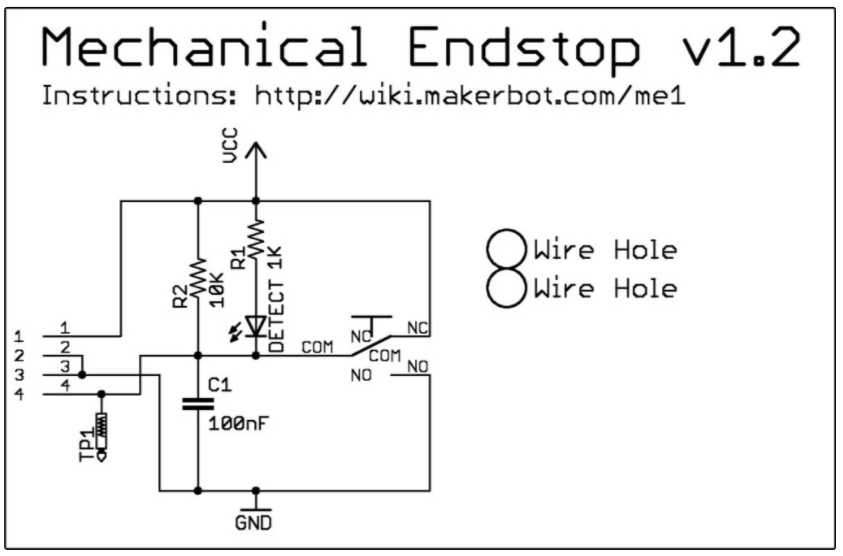
Although there's a wiki link on the board schematic, it has long since disappeared from the internet. Fortunately I was able to recover some key files from the wayback machine, and copied them here for reference (next 5 images credit: Makerbot):


Interface description:


The PCB layout:


Bill of materials:

PCB Render; "The Mechanical Endstop v1.2 is Open Source Hardware and is licensed under the GNU GPLv3":


I needed to measure and create my own mechanical drawing with dimensions:
The PCB supports are 5mm in diameter extrusions, 2.1mm high; The 2 holes are 3.1mm diameter (snug fit). The little nubs on the posts at the end near the connector are an addition 1mm high, 2.9mm diameter. 

I also ordered this Eccentric Work shop CNC optical limit switch isolator. Keep in mind that optical isolation does only that: isolate. This is not a switch debouncer. But then, we'll never need to debounce: the first limit trigger will freeze the controller board. All future signals, limit, G-Code, serial or otherwise will be ignored until the board is reset. 

See the EccentricWorkShop schematic:

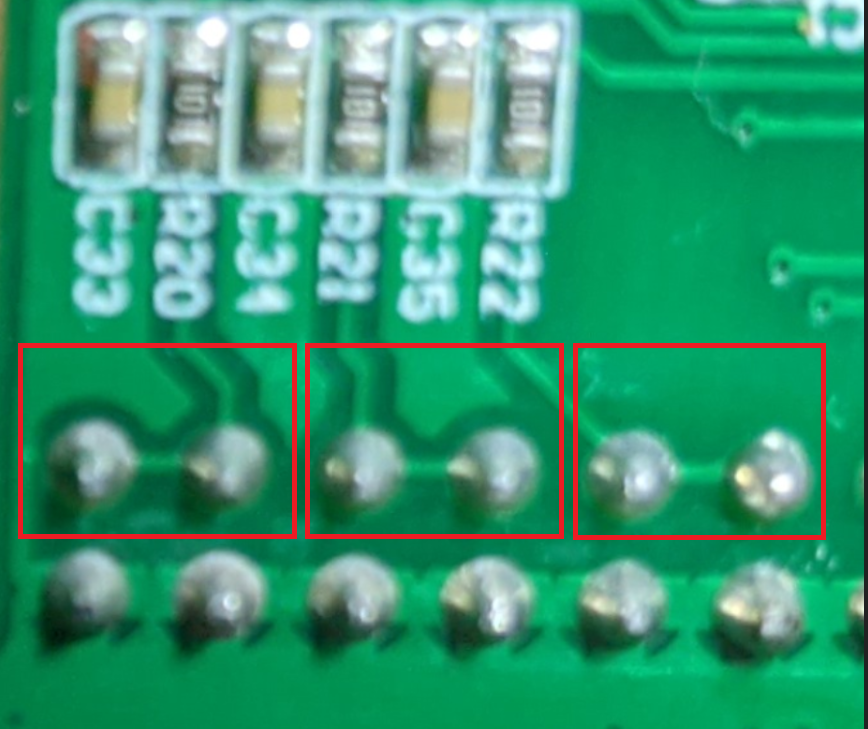
At one point, I thought I might need two of these isolator boards, as there is a connection for only 1 wire for each axis. However when looking at the schematic, it appears the limit switch detection is also tied together on the PCB:

And sure enough:


So it appears that when limits are detected, there's no way for the software to determine which limit switch was triggered for a given axis. Although the software would of course know which direction it last send a g-code, so perhaps it could be inferred. Still, if there was a malfunction, it might be nice to know which switch actually triggered.


2* Limit-X-Axis
2* Limit-Y-Axis
2* Limit-Z-Axis
A5 = Probe
A4 =
A3 = Coolant Enable
A2 = Cycle Start/Resume
A1 = Feed Hold
A0 = Reset/About
A7 =
A6 =
D13 = Spindle Direction
RST
5V

And from electrokean:

X = D9 = PB1 = pin 13 via R20
Y = D10 = PB2 = pin 14 via R21
Z = D12 = PB4 = pin 16 via R22

My first test drive was rather disappointing. After all that design work for the limit switch mounts, when using the stand-alone controller, nothing happened when running the sample G-Code and the limit switches were manually pressed. I would have hoped the woodpecker board would be interrupt-driven to detect the switch closures regardless of how the g-code arrived. There's a GitHub discussion where rseijo claimed "Zen, Yen & Xen had no connection points to the Atmega328" (confirmed to not be the case for me) and posted this useful header diagram:


As it turns out, the switches are not enabled by default! Thanks Anyzy for this useful tidbit:


Reading the fine print in the text block, we see that hard limits are enabled with $21=1 (of course they are). My $21 was found to be set to zero. Manually setting this to a value of 1 and tada! Upon pressing the limit switch while even manually moving the axis with the external controller, and the motion immediately stopped! See also the grbl documentation wiki.

Of course, there's probably a reason for having the feature disabled by default. Once triggered, all bets are off and the machine can only continue by pressing reset. Any work in progress is lost. Thus if any sort of stray noise or interference triggers the signal, well - that would certainly fall into the "undesired features" category; for example:
The machine stop working randomly with the spindle still running
And sure enough, if you see the settings posted, the $21 is already set on! So stray noise triggering these limit switches is definitely undesired.

I sure wish I had first found the Hackaday article that referred to an informative blog by Shahada Abubakar. One of the things I learned there: the reset switch is only one option to restart after a limit switch has been triggered. The other option:
 "This can be done by sending Control-X followed by $X"
There are additional tips on GRBL setting there, too.


Resources, Inspiration, Credits, and Other Links:


Find gojimmypi at gojimmypi.github.io

I'm currently working on my new blog home at  gojimmypi.github.io After implementing a variety of features such as dark mode , syntax hi...