This is a continuation of my previous blog, where I am working on improving the range of LoRa on the ESP32-based M5Stack module. Many thanks to Jimmy Lai that sent me a prototype of the next version of LoRa module!

Note my LoRa board arrived with no headers soldered on. There's not really room for a typical install of the usual jumper headers due to how thin this the module is. I still used the standard header, but given the limited space, I inserted the plastic on the reverse side of the board and snipped off the pins on that side.

I soldered from above. I can't remember the last time I did this - if ever. One thing to keep in mind is to use as little solder as possible, as quickly as possible. The solder will want to wick up the post, making them ever-so-slightly thicker. Also - if there's a glob of solder at the bottom, the jumper wire won't fit all the way, and we're already a little on the short side from installing the header on the other side.

Ready to proceed with the fun stuff...
Upon close inspection of this new LoRa board, there's a tiny ATMEGA328P sitting there! (yes, the same micro-controller in the famous Arduino Uno (see typical Uno schematic).
Unlike a "regular" Arduino, there's no need to cut the trace for "Reset EN". (regular Arduinos programmed with the serial port have DTR connected to reset with a capacitor that otherwise interferes with ISP).
This Mega328 has the 28 pin, MLF form factor:

See the full ATMega328 spec sheet here. This Mega 328 LoRa board is connected like this:

As shown, the Mega328 sits between the ESP32 core and the LoRa RA-02 transceiver. So the plan is interrupt driven LoRa that the Mega328 handles, while I2C will be used to exchange data from the ESP32 core and the Mega328. So before doing anything, this sounds complex enough to need a serious debugger.
Fortunately I already had an Atmel ICE debugger and Atmel Studio 7 installed. As a reminder, here are the instructions:
First: ensure the latest version of Atmel Studio is installed via Help - Check for Updates (I am using Version 7.0.1645). It may also prompt you to update the firmware in the ICE Debugger. (1.27 in my case). See Tools - Device Programming.
The most difficult thing is figuring out the pins to connect. Unfortunately the LoRa module has the ISP connections in a line rather than the standard connection. Adding to the frustration is the fact that the DuPont pins on the octopus cable have taped-on numbers. Although it is handy having the connections labeled, the thickness of the tape makes having 6 of them in a row a very tight fit:
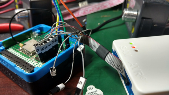
As a feature request, I hope the M5Stack folks consider implementing a standard SPI / ICSP connector:

The single most important thing is that: MO = MOSI = TDI (I wasted a bunch of time when I had assumed MO = MisO = TDO; which is not correct!). Also note that nTRST != nSRST. (yes, I made that mistake, too; my original screen clip did not include the SPI column which makes this more obvious).
These are the correct connections for debugWIRE, aka SPI, aka ISP programming of the M5Stack LoRa ATMEGA328P:

Note that VTG is not suited to power a remote device. This is a power sensor to determine logic voltage levels. Devices being debugged, including this LoRa module most be self powered!
For more information on the ICE Debugger, read the fine manual.
I started with a simple Uno sketch file:
void setup() {
  // put your setup code here, to run once:
  Serial.begin(115200);
}

void loop() {
  // put your main code here, to run repeatedly:
 Serial.println("hello");
}
Then in Atmel Studio: File - New - Project:

Select "Create project from Arduino sketch", edit directories as needed, then press ok. Next select the file location of the Arduino sketch. Be sure to select Arduino/Genuino Uno for Board:
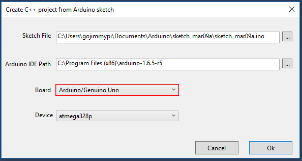
It may take a short while to create a project.


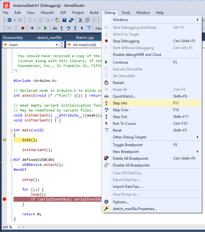
Next - click Debug - Step Into. The first time, there will likely be a warning about fuse settings:

Press Yes to set the fuses appropriately. If you get any other errors, check the wiring. Then recheck the wiring.
If successful, there will be a message that debugWIRE is enabled. BE SURE TO READ THE MESSAGE:

Note that you MUST power cycle the Mega328 (in our case the M5Stack & LoRa). Do not power cycle the Atmel ICE debugger.
Press ok, and VOILA!
I recall reading that the ATMega328 *must* have debugging properly disabled upon completion or Really Bad Things might happen (really?). I still do this, although I've never actually tested it to be sure. While paused at a breakpoint, click Disable debugWIRE and Close.

So the next step will be seeing if I can get the RadioHead drivers working on this new LoRa module... but first I'd like to get the LoRa AVR serial port working.
Resources, Inspiration, Credits, and Other Links:
- HTML Version of Atmel ICE Documentation
- AVR Tutorial
- Engbedded Atmel AVR® Fuse Calculator
- Updating firmware on USBASP bought from eBay
- USBasp - USB programmer for Atmel AVR controllers
- Atmel ICE
- Visual Micro Debugging
- Atmel ICE in Arduino IDE
- Atmel ICE User Guide
- AVR Freaks: Atmel-ICE unable to start a debugWire session


No comments:
Post a Comment
comments are disabled as nobody seemed to understand the no spam request.
See my latest blog at gojimmypi.github.io
Note: Only a member of this blog may post a comment.