With my newfound confidence in getting J-Tag debugging working with the Olimex ESP8266 I decided to revisit the first unit I bought - the Segger J-Link.
Let's first start by noticing the ESP8266 is nowhere to be found on the Segger supported device list page. But it is a standard JTAG device that when adhering to standards, Should work, no? Besides, I always enjoy a challenge.
It is cool Segger has an EDU (Educational) version for only $60(USD). A large discount over their base unit of $378, and massive discount compared to their $1000 J-Link Pro, (with of course different capabilities). Here's a screen snip from their web site comparing versions. (or visit the Segger Model Overview page for a more detailed comparison).
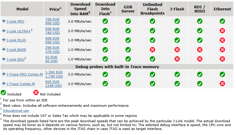
I really like that the EDU version is available to any hobbyist, not just students - just provided that you are not using it to make a commercial product for profit. Segger explains more on the terms of the EDU version on their web site. One thing to note is that there's no support other than forum questions.
The Olimex ARM-USB-OCD-H/ unit is also available for about $60 from Mouser Electronics - but they do not appear to have other more advanced units with more features. The Segger with Ethernet could be a really cool device to have one day....
So yes, I'm over $120 into a couple of hardware debuggers that I intend to use with a $3 ESP8266.
I first tried connecting my Segger to a NodeMCU with no success. VisualGSB seemed happy with the JTAG interface at project setup / test time, but not when actually programming.
For an easy increment step - I'll revisit prgramminh the $9 Olimex ESP8266 EVB shown in the SysProgs VisualGDB ESP8266 Tutorial, using the same pins:

The first thing that was immediately obvious, is that I like the Olimex having its own 5V power supply for their EDP8266 EVB board. The Segger does not have a power supply connector, however on page 420 of the J-Link manual - "Pin 19 of the connector can be used to supply power to the target hardware. Supply voltage is 5V, max. current is 300mA. The output current is monitored and protected against overload and short-circuit. Power can be controlled via the J-Link commander". I could not find the specs on the ESP8266-EVB (surely it is less than 300mA, eh?) - but I used a separate power supply for the Olimex ESP8266-EVB.
For reference: Pages 418 and 419 of the Segger manual* shows this table of JTAG pin definitions:

* (I've requested permission from Segger to include this)
As noted in my previous blog, I am following the Syslogs VisualGDB ESP8266 OpenOCD tutorial.
Success! The Segger *does* work in the same way as the Olimex ARM-USB-OCD-H to debug the ESP8266 - but my target is still the Olimex ESP8266-EVB. I really want to get debugging working on the NodeMCU as noted in this long and winding forum topic.


No comments:
Post a Comment
comments are disabled as nobody seemed to understand the no spam request.
See my latest blog at gojimmypi.github.io
Note: Only a member of this blog may post a comment.