Saturday, February 3, 2018

First FPGA Test Drive with Altera Cyclone IV

I decided to finally learn how to program an FPGA! Here are some first impressions and notes to self for future reference.


TL;DR

  • Blaster drivers need to be manually installed from C:\intelFPGA_lite\17.1\quartus\drivers
  • Cyclone IV board is EP4CE6E22C8; do not use default "auto device" (for Pin Planner) 
  • Verilog file added manually, module name must match file name and is case sensitive
  • Source files in the project are "Design Entities"
  • Do not insert to remove the USB Blaster ribbon cable while the device is powered on.
  • Download vendor board files here
  • JTAG programming of FPGA is temporary and lost upon power cycle

I ordered my first FPGA board - the Altera Cyclone IV EP4CE6 FPGA Development Kit and USB Blaster from the Numon Electric Cyberport Store on Aliexpress thanks to inspiration by Amitesh. He did all the footwork to find what seems to be the coolest Cyclone FPGA board that can still be programmed with the free version software. (note the really cool GX version with Nios processor needs software costing thousands of dollars)

If you order the board from Numon Electric, they have a download available on one-drive that includes a ton of really great documentation, sample code, and more. The file is called "RZ301 EP4CE6 development board.zip" however the contents of that zip file consist of mainly a single file "Altera Cyclone IV board V3.0.rar". Windows users will be annoyed that there's no native tool to easily extract RAR files. Having a linux VM or WSL will be handy here. The latest version of winzip also appears to now support RAR extraction.

Overall I was quite happy with the responsive customer service, prompt delivery, and quality of my new FPGA board. If you look close at the picture of my board, the actual silkscreen quality is much better than shown: the blur is from the poor picture.

While awaiting delivery of my Cyclone, I found this other tiny, inexpensive FPGA created by Luke Valenty. Note that if you order on the tinyfpga store web site, you can pay with Amazon, without having the hassle of creating an account, etc. This board is so cool, I think I will have a separate blog about it later.

Surprisingly, my Cyclone board arrived relatively quickly in only about 2 weeks! (the estimate at order time was 19 to 39 days)

In order to program the Cyclone board, the Altera Quartus Prime Lite software is needed. Unlike some other programs, installation was quick and easy.

IMPORTANT: Do not insert to remove the USB Blaster ribbon cable while the device is powered on. There was an included warning that the board would likely be damaged. I did not test this.

The USB Blaster was not Plug-N-Play, and Quartus Prime did not see it:


A quick google search indicated that the drivers need to be manually installed; instructions copied from Altera site here for reference:
The Altera On-Board USB-Blaster II cable appears as Altera USB-Blaster (unconfigured) when first attached to your system. After it has been configured by the Quartus Prime software, it will appear as Altera USB-Blaster II (JTAG interface) and then Altera USB-Blaster II (SystemConsole interface). You might need to install drivers for each of these interfaces; follow the steps below to install the drivers.

You must have system administration (Administrator) privileges to install the USB-Blaster and USB-Blaster II download cable driver.

Driver Installation for Altera USB-Blaster

  1. Plug the USB-Blaster download cable into your PC. The Found New Hardware dialog box appears.
  2. Select Locate and install driver software (recommended).
  3. Select Don't search online.
  4. When you are prompted to Insert the disc that came with your USB-Blaster, select I don’t have the disc. Show me other options.
  5. Select Browse my computer for driver software (advanced) when you see the Windows couldn’t find driver software for your device dialog box.
  6. Click Browse, and browse to the <Path to Quartus Prime installation>\drivers\usb-blaster directory.
    • Note: Do not select the x32 or x64 directories.
  7. Click OK.
  8. Select the Include subfolders option, and click Next.
  9. If you are prompted Windows can’t verify the publisher of this driver software, select Install this driver software anyway in the Window Security dialog box. The installation wizard guides you through the installation process.
  10. When The software for this device has been successfully installed dialog box appears, click Close.
  11. To complete your installation, set up programming hardware in the Quartus Prime software.

Driver Installation for Altera USB-Blaster II

  1. Plug the USB-Blaster II cable into your PC.
  2. Open the Device Manager, and right-click on the Unknown device under the Other devices branch.
  3. Select Update Driver Software.
  4. Select Browse my computer for driver software.
  5. Enter the location of the Quartus Prime software USB-Blaster II driver files directory (<Path to Quartus Prime installation>\drivers\usb-blaster-ii) in the Search for driver software in this location field.
  6. Click Next.
  7. Click Install in the Would you like to install this device software? Windows security dialog box.
  8. Close the Update Driver Software - Altera USB-Blaster II (Unconfigured) successful installation notification. The Device Manager now shows a new branch called JTAG cables with an Altera USB-Blaster II (Unconfigured) node.
  9. Open the Quartus Prime Programmer. Within a few seconds, the JTAG cables branch displays two nodes: Altera USB-Blaster II (JTAG interface) and Altera-USB Blaster II (System Console interface).

The pin-out of the USB Blaster cable is such that it can be used for three different programming modes: AS, PS and JTAG, as shown in this pin definition table from the Intel FPGA USB Download Cable User Guide:


The important thing to note here is that programming via JTAG is temporary! My board came pre-programmed with something that cycles though the 4 LED's on the board. There's always a little fear of sending a new program that toasts your new FPGA (yes, this is absolutely possible!). So it is cool that upon power cycle, the original config is loaded back into the FPGA to confirm all us well. Fortunately my first program actually worked the very first time!

As with all development environments, Quartus has its own annoyances. I found it very difficult to simply: File - Create New Project and get something to actually work without a bit of fussing.

The first annoyance is the default directory. For example, in Visual Studio, the IDE is smart enough to know to actually create a directory for your project. Any you only need to type it once. Here, the default directory is the IDE, and projects are created there unless explicitly stated in THREE places. So the new Project Wizard starts here:


Be sure to append a project name to the directory:


Or better yet, I keep all my project in c:\workspace\ in this case for the new myFPGAgizmo project:


You can set the default location in: Tools - Options - General - Default File Location.

I created an empty project...


and did not add any design files...


This next step is important... the default device is set to "Auto". What this does is completely disables the Pin Planner feature needed later, giving an error:
Cannot display Pin Planner the current Compiler settings assign an AUTO device.
For a newbie like me.. the solution was not very obvious. To avoid this, change the default at new project time to EP4CE6E22C8


The tools are left as default:


On the final Project Wizard page, the summary is shown:
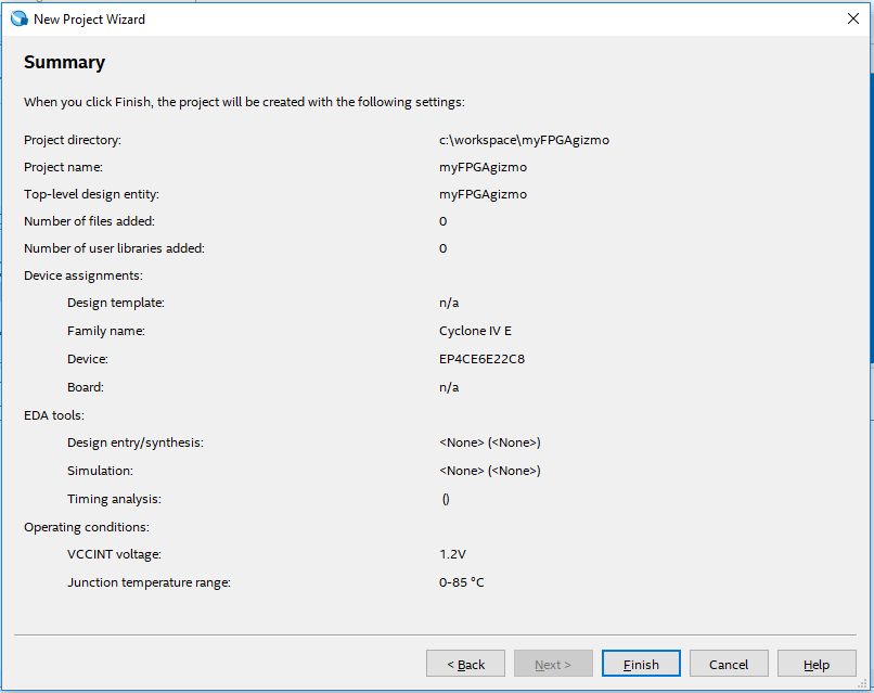

Tada! All done, right? Nope. The "Wizard" still does not actually complete a project.

Double-click on "myFPGAgizmo" to edit the code, and a nice, less-than-intuitive error pops up:
Can't find design entity "myFPGAgizmo".
Not exactly to most intuitive error message for a newbie. 


Good luck finding "Add Design Entity" in the menu. Here, you just need to know that a new Design File needs to be manually added (why the wizard does not do this, I do not know).

So from what I can tell:  a source "File" == "Design Entity".

File - New - Verilog HDL File:


Quartus does not give you an opportunity to name this file when it is first created. Only at save time will it prompt to give it a new name. Visual Studio users will not be impressed.


Now another important note: The name of the module MUST MATCH the name of the "top level" file name, and it is case sensitive. The "top level design entity" is that file first listed. You just need to know this. Otherwise the Quartus software gives the less-than-intuitive error message:
Top level design entity "myFPGAgizmo" is undefined 
Here the "myFPGAgimoName" needs to be the same as the file name "myFPGAgizmo":


So after dealing with those annoyances the learning curve, I was finally able to write some Verilog that I found in another tutorial (see page 14):


module myFPGAgizmo (x1, x2, f); 
  input x1, x2; 
  output f; 
  assign f = (x1 & ~x2)|(~x1 & x2); 
endmodule 


This is where things get interesting. It is one thing to write some code, but getting it to interface to the real world is what makes it fun! Normally I/O is abstracted through complex device drivers and API calls. However, it does not get much more direct in FPGA programming, as the actual pins on the chip are assigned to variables in our code! Even better, there's no bizarre renumbering that I find ridiculously frustrating in the world of Arduino programming. There's a single pin number. Ahhh. What bliss.


As can be seen in the schematic, Pin 87 is LED4, and Pins 88 and 89 are tied to keys (button switches) KEY1 and KEY2 (but yes, instead labeled S1 and S2 on the board). Yes, those are the actual pins numbers on the Cyclone IV - pins 87, 88, and 89. No big deal, right? Well, sure - but apparently not all engineers agree. Just google "pin numbering arduino" to see how many hours have been lost to frustrating abstracted re-numbering.

Once code is entered, it is compiled using the menu: Processing - Start Compilation. When the pins are not actually assigned, there will be a compiler warning:

Critical Warning (169085): No exact pin location assignment(s) for 3 pins of 3 total pins. For the list of pins please refer to the I/O Assignment Warnings table in the fitter report.
Click on Assignments - Pin Planner. (recall above, we explicitly assigned our chip part number, otherwise this feature is not available).  If you double-click in the Location column, a drop-down list will appear:


We need to assign the pins to keys and LED as shown in the schematic:


Simply close the Pin Planner and compile again. We're ready to send the FPGA code to our device!

Note the USB Blaster connection in the very first picture on this page.

Click Tools - Programmer. If the currently selected hardware says "No Hardware", click the "Hardware Setup" button (make sure your device is plugged inn, and drivers installed)....


In this case, I selected the USB Blaster by double-clicking on it.

To send the FPGA code to the device, select "Processing - Start" (or simply press the "Start Button"). If successful, there will be an indication in the progress box:
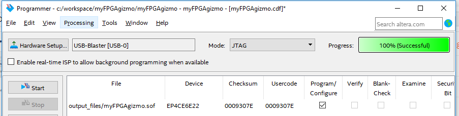


That's it! There's now an XOR gate programmed in the FPGA. Press S1 or S2 to have the LED got out. Press both or leave both unpressed and the LED1 will be illuminated. Cool.

Note we've programmed the FPGA via the JTAG connector on the board. When the board is power cycled, we'll lose these changes and the board will revert back to vendor ship default.


Note that if you find cheap Cyclone boards on flea bay, the most recent version of Quartus does NOT support the older chips! I sadly learned this after buying a cheap, bare-bones Cyclone II and then noticed it was not listed as a device option in the Quartus IDE. The latest version supporting the Cyclone II is Quartus version 13.0sp1 from 2013. (I wonder if side-by-side installs are supported? I didn't try)

Here's a chart of supported devices vs Quartus versions specifically the Cyclone series:


That's it for now... send me a message on twitter if you have any feedback / suggestions / notice any typos.


Resources, Inspiration, Credits, and Other Links:


Monday, January 1, 2018

Sino:bit Test drive & attempt to single-step debug with OpenOCD and GDB

Sino:bit - Arduino, OpenOCD and GDB?


A little while back, I responded to an offer to get a free Sino:bit from the nice folks at Elecrow. Well, it was not completely free; I paid $4 for shipping from China, as it was not really practical for me to pick it up. ;)

In case you've not heard - this is the Chinese version of the BBC Micro:bit - or more precisely, based on the Calliope mini, which is based on the Micro:bit. Me... I'm in favor of pretty much any technology that may help inspire the next generation of programmers.

Although there are a variety of ways to program this device, I followed along with the Adafruit instructions to use the Arduino IDE (and/or the VisualMicro add-in for Visual Studio).

Initial programming was really quite easy. There was one little instruction missing from the Adafruit site. Hopefully they will notice my tweet and make the correction. In short, the Arduino HT1632 libraries need to be manually added. So if you see an error like this:


...then simply add the library:


I like to turn on verbose compiling and uploading:


When doing so, a successful upload will look like this:


In particular, I noticed that a forked version of Open OCD is used to upload the sketch. The first thing that comes to mind when mentioning OpenOCD, is of course GDB! So I thought I'd see if I could get some single-step debugging working without the need for a potentially expensive hardware debugger.

One line to notice during the verbose compile / upload is the last line of the compile. Note that a unique directory is created for the binaries. In my case: ~\arduino_build_91191

The full line from my Arduino IDE looked like this:

C:\Users\gojimmypi\AppData\Local\Arduino15\packages\sandeepmistry\tools\openocd\0.10.0-dev.nrf5/bin/openocd.exe -d2 -f interface/cmsis-dap.cfg -c ; -f target/nrf51.cfg -c program {{C:\Users\GOJIMM~1\AppData\Local\Temp\arduino_build_91191/sinobit.ino.hex}} verify reset; shutdown; 

In order to launch OpenOCD to simply listen, and not upload - minor modifications are needed. Remove everything after and including the "-c program":

C:\Users\gojimmypi\AppData\Local\Arduino15\packages\sandeepmistry\tools\openocd\0.10.0-dev.nrf5/bin/openocd.exe -d2 -f interface/cmsis-dap.cfg -c ; -f target/nrf51.cfg  

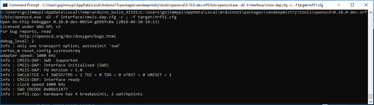
Upon launching this in a DOS window, the resulting output looks like this:


Note that OpenOCD will not exit. It is waiting and listening for a GDB connection.

In my case, I could not find a suitable Windows GDB executable. So I ventured into the land of WSL - specifically Ubuntu. (I also wrote a little blog on OpenOCD on WSL Ubuntu). Once a local Ubuntu is installed an operational, GDB can be added:

sudo apt-get install gdb
Note that in WSL Ubunto, there's no C:\ drive and the slashes all go in the opposite directions. I went to my specific directory created by the Arduino IDE:

cd /mnt/c/Users/gojimmypi/AppData/Local/Temp/arduino_build_91191


GDB is launched like this:
gdb -d ./ -d /mnt/c/Users/gojimmypi/AppData/Local/arduino15/packages/sandeepmistry/hardware/nRF5/0.4.0/cores/nRF5 -f sinobit.ino.elf

If all goes well, when GDB is running and accepting commands, if will look something like this in the WSL Ubuntu window:


Due to the oddities of Windows vs Linux, I first ran these commands:


# C:\ is found in /mnt/c
set substitute-path c:/ /mnt/c

# There was an odd case problem in Arduino15 vs arduino15
set substitute-path /mnt/c/Users/gojimmypi/AppData/Local/Arduino15/ /mnt/c/Users/gojimmypi/AppData/Local/arduino15/

# make really sure the current directory is used
directory ./


Then connect:
target remote localhost:3333
monitor reset init

The resulting GDB window in Ubuntu should look something like this:


The OpenOCD DOS window should have updated, and look something like this, showing the successful connection:


At this point, things are really exciting! Ready to debug? Sadly, no. Typing the GDB "step" command results in the dreaded message:

Cannot find bounds of current function

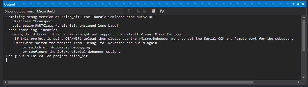
I also tried to use the VisualMicro add-in for Visual Studio, no joy there, either:


Although it certainly works to compile and upload code in "release" (no single-step debugging) mode:


@TheFlyingSephyr also suggested trying the Embedded Studio IDE with the Segger hardware debugger. Perhaps another blog for another day...

On a side note, it might me interesting to peek at the elf file:


sudo apt-get install binutils
readelf -a /mnt/c/Users/gojimmypi/AppData/Local/Temp/arduino_build_91191/sinobit.ino.elf


In the end, it seems that you simply can't get to there from here when attempting to debug a "soft device".  :| If you have any ideas, please leave a comment or send me a message at gmail.

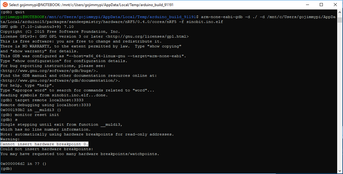
UPDATE: I've had a few replies regarding other debugging options. In particular a tweet from Tomas indicating that perhaps Mbed tools might help. Indeed there's some interesting info that shows using arm-none-eabi-gdb and pyOCD. Although I was able to get that toolchain installed and working:


I was not able to actually get single-step debugging working (nor does the Mbed instruction page indicate this is even possible). Note the error:

(gdb) step
Warning:
Cannot insert hardware breakpoint 0.
Could not insert hardware breakpoints:
You may have requested too many hardware breakpoints/watchpoints.

As show here:


Another more promising method (although considerably more complex and potentially expensive) - would be the hardware debugging method using JTAG. One of the key things needed here is of course is how to connect the debugger. Many thanks to Elecrow for the prompt reply on twitter for information on the Sino:bit JTAG pins:


What you cannot immediately see from the silkscreen is that those are pads and not through-holes. Another item on my wish list for version 2! (ok, let's make the proper wish: how about a actual header for JTAG connector!)

I'll create another blog page for the Sino:bit JTAG. My first attempt will be using my $2 Blue Pill STM32F103 board converted to a Black Magic Probe.

Overall the Sino:bit seems very cool, despite the problems with OpenOCD and GDB. It would be awesome if some sort of single-step debugging was possible - bit that certainly is not a showstopper. Most people, certainly not beginners - would never even attempt this type of debugging. Other changes I would make would be having a less intensely bright power LED, and making the 12 x 12 grid of LED's multi-color.


Resources, Inspiration, Credits, and Other Links:

Tuesday, October 24, 2017

ATECC508A Embedded Crypto - AWS costs

TL;DR;  Dont leave aws_interact_gui.py running!

In my previous post, I wrote about my first impressions setting up AWS.

This is just a quick blog post to show my crazy AWS charges after just a few days. Actually, not so much the cost, but the number of messages:


Note that my AWS IoT monitor has recorded less than 20 connections.


Also on that page, just a bit further down - shows I've only published a few hundred messages:

And only 2 rules executed:


Yet somehow, I've been charged for hundreds of thousands of "messages". The curious thing, is they are listed under the "Shadow Message".

So ok - 2 bucks is not a big deal... but scale that for more devices and more than a few days - and the costs get out of hand really rather quickly.

I've posted a message on the AWS forum requesting help in understanding these charges. I'm wondering if simply launching the shadow monitoring page... if there's perhaps there are repeated messages from the browser to my device such as this shadow monitor:
I've contacted AWS billing, but they have "limited access" to give me any more details as to exactly how those hundreds of thousands of messages occurred.

Fortunately, the folks at Microchip are super responsive. I had an answer within hours! (Thanks, Ben!) The forum answer copied here:

The demo GUI (aws_interact_gui.py), polls the GetThingShadow (http://docs.aws.amazon.com/iot/latest/developerguide/API_GetThingShadow.html) API function to show the current shadow state. However, if left running, its polling period of 500ms could incur a lot of messages.

This polling method was not intended to be an example of how an IoT system would interact with the devices, but just a quick and easy way to display the state. Typically, one would use the IoT rules engine to trigger other actions within AWS:http://docs.aws.amazon.com/iot/latest/developerguide/iot-rules.html
We're looking into changing how this script works so leaving it running doesn't create so many messages.

So the super important take-away here is to NOT leave the aws_interact_gui.py running (at least not until updated)! At 500ms intervals (2 per second), that would be 31*24*60*60*2 = 5,356,800 messages per month! Even at $5 per million messages, that's $30 a month just to leave the diagnostic app running.

Stay tuned... I'm now digging into the RTOS code which is really quite interesting :)


Saturday, October 14, 2017

ATECC508A Embedded Crypto - Next Impressions setting up AWS

The state of Internet of Things (IoT) Security is a disaster. Hardly a day goes by without news that some new product is discovered to also have some ridiculously glaring security problem. There's a potential solution: a "security in a chip" device for less that a buck, that could seriously change the landscape of IoT security.

In my previous post, I took the MicroChip AT88CK590 for a brief initial test drive. Although cool in concept, I was initially frustrated and underwhelmed. I didn't even get around to posting my experience for a couple of months. (in part, as I never actually got it doing what I wanted) Note that was with completely different eval hardware.

This time around I am looking at the much more elaborate Zero Touch Secure Provisioning Kit for AWS IoT. Be sure to pay attention to the "-B" suffix. A similar part number at mouser is marked as "End of Life: Scheduled for obsolescence and will be discontinued by the manufacturer." You can try this link to see if they eventually carry the update.

 AT88CKECC-AWS-XSTK-B, image from MicroChip


However, when I did finally post that blog page and tweeted it - I got the attention of the folks at MicroChip. In particular their response regarding the a new and interesting crypto chip AWS walk-through that I had not seen:

http://microchipdeveloper.com/iot:ztpk

I starts out really quite interesting! The steps are very clearly documented regarding all the (less-than-intuitive) AWS setup details. At the end of the story though, right before the culmination of anticipated technical details, it abruptly ends. I was really hoping for a code walk-through as well. Alas there was just a single "Explore" bullet item:
  • "Firmware that comes in the ZIP to see how the ARM SAM G55 communicates with the secure element (ATECC508A) and the Wi-Fi module WINC1500"
So, ok. I'm good with doing my own code analysis. Sometimes the comments are better than an external document walk-through anyhow.

There are a ton of links throughout the rather long instruction set. By the time you get to the end when reading, perhaps the Zero Touch Secure Provisioning Kit Software Files was missed way up at step 2. I had see that, even clicked on it. But it initially looks like an ad, complete with the "Buy It Now" button in the upper right corner. But the software is there! Scroll to the bottom and click the "Getting Started" tab:


Then click on the "Get the necessary code HERE" link:


I would have included the link, but it goes to a wonky "Software Copyright" page where you need to provide a name, email, company info. You can however, then immediately download the software. (unlike some sites where you need to wait for confirmation email, bla, bla).

I had a very difficult time with this: several times when I downloaded the file, it was less than 50KB and windows reported that it was correupt when trying to open it. Fortunately my twitter thread ended up with an offer to talk with someone at MicroChip! Later that day I had a great phone conversation with a rep from MicroChip that completely re-invigorated my interest in their crypto chip! He also helped with the download. What worked for me is copying the (apparently time-sensitive) link to clipboard... closing google chrome... and then pasting into a new chrome instance. I think there may have simply been a problem with the timing/loading of the javascript for the page. In any case the file starts downloading immediately. It is about 13MB in size.

The two main components of the zip are the (1) python scripts for setting up AWS and (2) a SAMG55 Atmel Studio Project called AWS_IoT_Zero_Touch_SAMG55.atsln

It is unfortunate that the code is "protected" behind a copyright notice. It really belongs as open source on github. Hopefully MicroChip will change that soon.

I suspect the folks at AWS are really quite happy to see they are the only IoT service listed! lol


The microchipdeveloper site is of course still a work in progress. I hope to see a lot more providers in the future. I've always been wanting to use AWS for my MQTT data anyhow: In part, well, it is MY data. I had tried the very easy to use Adafruit.io - but some time back it was offline for a long stretch. (granted it was still beta) But also - it has limitations on number of devices (5) or pay $120/year for up to 60 devices (not yet available), and show stopper: the data was out of my control. The cool thing about adafruit.io was that I could use insecure MQTT of plain HTTP with my ESP8266 (well, duh, back to the proliferation of insecure IoT, eh?) AWS is definitely more challenging in not even allowing anything but a secure connection.

One thing to point out about installing AWS CLI for Windows is that at the end of install, nothing happens. No new icons, no message of completion. Nothing. For me, the "AWS Tools for Windows" listed under Amazon Web Services in Windows 10 start menu - was something I installed last year.

To confirm AWS CLI installed correctly, simply pop into a DOS window and type "AWS":


Microsoft Windows [Version 10.0.15063]
(c) 2017 Microsoft Corporation. All rights reserved.

C:\Users\gojimmypi>aws
usage: aws [options] <command> <subcommand> [<subcommand> ...] [parameters]
To see help text, you can run:

  aws help
  aws <command></command> help
  aws <command></command> <subcommand> help
aws: error: too few arguments

C:\Users\gojimmypi>


The Python install is a little tricky for me. I already had V2.7 installed (for something that explicitly wanted that version)... and to add V3.6.3 to my path... well, I'm sure I'll bump into that at some unexpected point in the future. This is a good reason to perhaps have a VM for each development environment.

The comment "May take a while to install." should not be underestimated for the pip install step! They should change the text to: "Takes a ridiculously long time, and may seem to stop at times!" lol!

Another place to note a possible problem is on creating roles in Section III. I think the AWS console changed a little since the MicroChip instructions were created. Here's my AWS Console:


Note the "AWS Service" is selected (no radio button) and the service is called simply "Lambda" (not AWS Lambda). Next Step is actually labeled "Next: Permissions"

The final resultant JITR policy also looks a bit different from the walk-through.


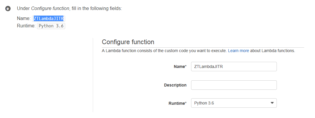
My function "Author from Scratch" was also a bit different than instructions:

Instructions:


What I saw:


And here's what my actual code looks like in the function:


The instructions refer to "Rules"... it is now called "Act". Note there's an identical icon, just a different name (instructions on left; my AWS console on right):


The instructions also show running a python script as easily as if it were a batch file. I needed to use the word "python" before the script name:


I received an annoying error:


I wasted a ton of time before I realized somehow Windows 10 "set time automatically" was turned off! Argh! So a click of an option setting and VOILA! Success.

<happy dance>!!</happy dance>

Next, I will finally take a look at the code!

Check out my next post on my first bizarre AWS costs.


Tuesday, October 10, 2017

ATECC508A Embedded Crypto - First Impressions

Having an embedded crypto chip to offload SSL processing for say, an ESP8266 sounds really quite interesting - particularly a solution that could be housed in a package as small as a tiny 3-Lead SOT-3 package! Wow, how cool would that be to help solve the problem of plain text IoT devices on devices with limited processing power and memory?

First, I'd like to thank @MartyMacGyver for his time and assistance in helping me to better understand the Atmel crypto chips and related development boards. Be sure to see see his CryptoAuth-explorations. As with his information, this project is neither affiliated with nor sponsored by Microchip / Atmel.

My AT88CK590 from Mouser Electronics arrived last week! (erm, by the time I published this, actually a couple of months ago). Atmel has apparently not heard of "Frustration Free Packaging". Petty cardboard complaint aside, even the cheap plastic USB cap was very difficult to remove. Alas only twenty bucks, but you'd think that they'd want to make a better first impression with a developer kit, eh? Besides, you'll probably want to pry it open anyhow. I took a soldering iron to mine and flattened the bumps that hold the USB cover in place to make it easier to remove.

I first upgraded Atmel Studio (Help - Check for Updates). That took quite some time. Next I installed the ACES 5.0.0 Setup from the ATT88CK50 page. You must have a device to use the software. Otherwise nothing but the "No devices" dialog box:


Once you plug in the device, the dialog box will change:


Note that the AT88CK590 USB dongle has 3 different security chips on it, each with 3 different I2C addresses. These three chips are controlled by the onboard ATmega 8-bit Atmel AVR® AT90USB1287 microcontroller. The complete AT90USB1287 datasheet is a whopping 456 pages long, There's also a summary datasheet that's only 39 pages. The schematic diagram is likely useful for review.

The important thing here: when test driving the crypto-chips directly on the USB dongle, code will target the ATUSB1287. Code will also need to be portable to your target MCU,

While reviewing the schematic, you'll see that the USB port talks *only* to the MCU, Only the MCU talks on the I2C bus to the security devices. Thus if you put different firmware on it, you could well find yourself no longer able to use the ACES software to talk to the security chips. Program with caution!

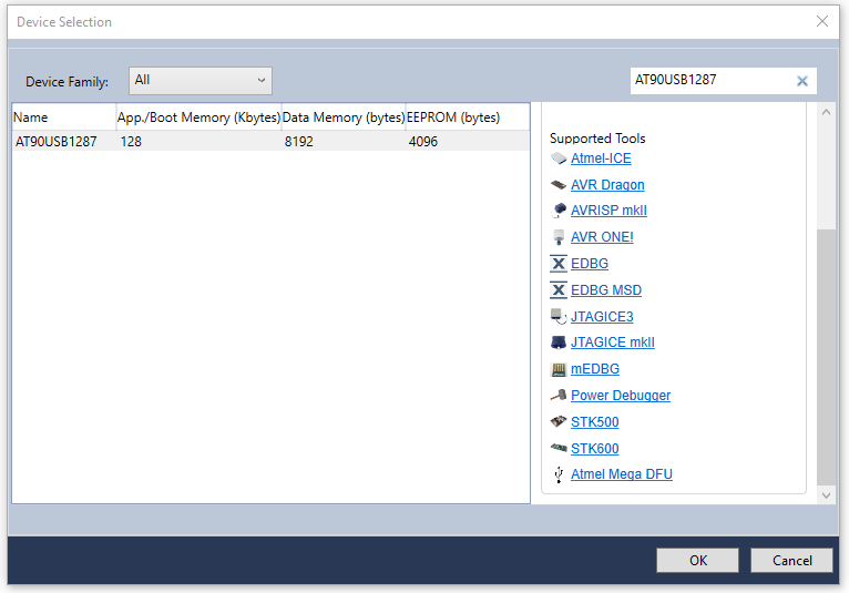
As a side note, when using Atmel Studio, here's a list of the supported programming tools for the ATUSB1287. Probably the most important one is that last DFU item.


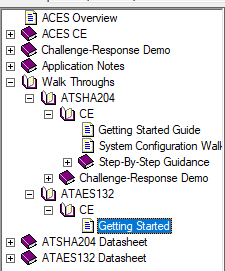
The so-called "walk-through"s in the AECS Config help were less than impressive. I swear the help looked the same as those found in Windows 3.1 - and worse: the contents also did not fully match my app. For example: there was no green indicator for system status:


Next, there was no mention of the most important point - that the Key ID number for step 2 needs to match Key ID in step #3.  Obvious of course once you know this - but for first time users following a Walk-Through... hmm.


So anyhow, type a challenge phrase, press the [Execute Nonce] button, then [Execute Mac] then [Execute CheckMac]. If successful there should be a Matched status.

The ATAES132 walk-though is even less complete & less helpful.


There's only online help for 2 of the 3 chips: the ATSHA204 and and ATAES132. Of course my ATECC508A is not listed. :|  The only reason I ordered this evaluation kit was to take that chip for a test drive. After a bit of digging, I eventually discovered "The ATECC108A and ATECC508A are supersets of the ATSHA204A and thus upward compatible". I was unable to find a full datasheet for the 508 - however once knowing that it is a superset of the ATSHA204A, one makes the assumption that the datasheet is (hopefully) "similar enough" to the 508.

An important piece of information in the ATSHA204A datasheet (page 14, Section 2.1.3):
"The OTP zone of 64 bytes (512 bits) is part of the EEPROM array, and can be used for read-only storage. 
Prior to locking the configuration section (using lockConfig), the OTP zone is inaccessible and can be neither read nor written. After configuration locking, but prior to locking of the OTP zone (using lockData), the entire OTP zone can be written using the Write command. If desired, the data to be written can be encrypted. When unlocked the OTP zone cannot be read."

Once you start the AECS Config tool, it appears there is no way to select a different chip to test drive. So exit and restart the app to choose a different one.

Upon restarting and selecting the 508, I was not able to get the Verify Mac to work. It appears that although the other two chips are pre-configured, this one is not. That may be expected in the stand-alone chips. I had asked mouser if I could buy individual quantities of the ATTEC508A-SSHAW (the ones pre-configured for AWS) - but unfortunately they responded indicating that they could not break the 4000-piece reels. Still I would have expected the  ATT88CK50 to arrive pre-configured with something even if the individual 508's that I also bought were blank.


So also take note of the downloads on the Atmel site. The first two code samples after the ACES software are for the ATSHA204 chip, not the ATECC508A.

The last download, the Atmel-CryptoAuth-AT88CK590_Project-C-code.zip has over 3000 files. Alas that too, seems to be limited to the SHA204 and AES132 libraries. Cool if that's what you are looking for, but I was hoping to dig into the new '508s (the third and most interesting of the chips!)

So back to the Atmel/Microchip web site... <sigh> and I came across this page on ECC-based Crypto Elements. Clicking on "start now" takes you to yet another crypto page. Chasing the links and you'll find the AT88CK101 Development Kit. Finally on THAT page, there's a link to the CryptoAuthentication ATECC108A/508A Development Library 1.2.1 download. This is the eccX08_library-150525 with a brief README and some C header and source files; not much of a walk-though here, but code is interesting.

As for the AT88CK101 - well Mouser has 6 similar but different products listed, Each are about $90 but none of which list the ATECC508A. So I'm not sure if it would be useful or not with the '508.

Continuing to chase the links, you'll see further down on the Start Now page, that there's a link to CryptoAuthLib.  And on THAT page, there's a link to the CryptoAuthLib Firmware Library 20160108. This is a 12MB compressed zip with many more interesting files. I'd start with the .\cryptoauthlib\docs\README.pdf then move on to .\cryptoauthlib\docs\html\index.html where there's finally some good docs! Also see there's a doc tab, with even more downloads.

I was not able to find this code in the Atmel github repository, nor the MicroChip github respository. However, MicroChip does have this github cryptoauth-openssl-engine repository that is definitely worth a look. The README there starts out with: "This is an OpenSSL Engine implementation using ATECC508A for ECC key storage, ECDSA sign/verify, ECDH, and FIPS Random Number Generator" and there's a cool wiki as well.

After finding the MicroChip github, I realized that there's an entirely different subset of documentation and downloads for the ATECC508A available, separate and different from Atmel. Apparently a cohesive and consistent web site has not been a priority after the acquisition.

I really prefer that code be available on github, rather than zip downloads. So I copied what I believe are the most relevant source files to my own atmel-code repository. My github clones are stored in \workspace\ directory, so be sure to start with:

\workspace\atmel-code\cryptoauthlib\docs\html\index.html

After getting all this installed, I just happened to be lucky enough to be on the github notification email alert for issue #1 and there.. a link in the MicroChip site to this updated CryptoAuthLib gem (updated  July 5, 2017). Note the CryptoAuthLib link above, specifically the  Atmel-CryptoAuthLib-Firmware_20160108.zip is noted on this new page as "Not recommended for New Designs" - note there's also no indication of this new firmware on the Atmel CryptoAuthLib page!

If you download that updated zip file - in the README.md there's a note to watch the CryptoAuthLib documents (on the Atmel site) for "new examples coming online". (as of the timw of my writing this, there's noting newer than January of 2016). I wonder why MicroChip would post new code on the Atmel site, referenced from a download from the MicroChip site?

Revisiting the mod topic, the Atmel Flip 3.4.7 as mentioned here does not seem to work on Windows 10. Both the "requires Java Runtime and "Jave Runtime Included" return an error message:

The newer (January 2017) flip program on the MicroChip site is actually an older version 2.4.6 from 2002 that only supports a limited number of chips such as the 89c51 series.

Fortunately I happened to already have a Windows 7 machine setup in a VMWare Workstation, Upon running the same setup there, I was able to get the Flip utility working. However not much more than that - as after selecting an MCU, I received this error complaining about a missing libusb0.dll


The issue here, is that apparently the Atmel drivers needs to be manually installed/updated. Once again, thanks @MartyMacGyver for the tips on replacing the AT90USB1287 drivers on Windows 7. Here, just go to Control Panel - Device Manager. Right-click on the Atmel Device and select "Update Driver Software...".


Then manually select the Atmel Flip directory:


(as usual, you may be prompted to reboot)

Curiously, not only do I have the Java Virtual Machine problem on Windows 10, but I also don't see the Atmel device listed anywhere in device manager. Windows 10 *does* see it, as I am able to go into VMWare workstation and connect the host device to the Windows 7 VM. Hmm.. I'm not sure I want to fire up a Windows 7 VM every time.

So at this point, I am really quite underwhelmed, unimpressed, and rather disappointed and frustrated. I am also however - rather relentless. A bit of googling and of course I immediately found others with the same problem on the avrfreaks site. Fortunately the AT90USB1287 is DFU Bootloader Capable, and my old friend avrdude is a DFU loader! There are a variety of avrdude tutorials out there, including this one from lady ada. If you have the Arduino library installed on Windows, you likely have avrdude installed here:   C:\Program Files (x86)\Arduino\hardware\tools\avr\bin (and it likely will not be in your path).

The first thing we'll want to do is read and save the firmware!


"C:\Program Files (x86)\Arduino\hardware\tools\avr\bin\avrdude.exe"
"C:\Download\Atmel\Atmel-CryptoAuth-AT88CK590_Project-C-code_1-0-5\DevelopmentKits\AT88CK590\CombinedLibraries\AtmelStudio6\CombinedLibraries\OutputConfigDefault\"

gives an error:


avrdude.exe: can't open config file "": Invalid argument
avrdude.exe: error reading system wide configuration file ""

so I tried on linux (Ubuntu)


avrdude -pusb1287 -cflip1 -Uflash:r:read-usb1287:a

different error:


avrdude: Error: No matching USB device found
avrdude: AVR device initialized and ready to accept instructions

Reading |                                                    | 0% 0.00savrdude: error reading signature data for part "AT90USB1287", rc=-1
avrdude: error reading signature data, rc=-1

avrdude done.  Thank you.

it appears that when plugged in, there are 2 new /dev/ items:

/dev/hidraw1
/dev/usb

I tried to change permissions, no luck there.


sudo chmod 777 /dev/usb
sudo chmod 777 /dev/hidraw1

Same avrdude error. A bit more googling and I found this note that you need to first boot the usb1287 into DFU mode. As yes, just as @MartyMacGyver described in his wiki on entering DFU mode. After chasing documentation and other software issues, I had almost forgotten about his great walk-through that includes valuable DFU info.

I simply want to have an embedded solution for SSL. They certainly don't make it easy. Just out of curiosity, I thought I'd poke around and see what sort of alternative solution might be available. One of the tools appears to be the AT88CK9000 Secure Personalization Kit. Alas, that too turned out to be a comedy of "not available":


I at least found them at Mouser. There are 2 options: $374 for the 3 lead SOT23 package, oh - but $499 for the 8 pic SOIC package, currently "on order".


Ok, so back to getting the device into DFU mode. Looks like I will need to jump in with both feet with no return.

again with avrdude, this time in DFU (you'll know DFU mode by seeing only the red LED illuminated; all the blue crypto LED's will be dark.

avrdude -pusb1287 -cflip1 -Uflash:r:read-usb1287:a


results instead with:

avrdude: AVR device initialized and ready to accept instructions

Reading | ################################################## | 100% 0.02s

avrdude: Device signature = 0x1e9782 (probably usb1287)
avrdude: Error: "lfuse" memory not accessible using FLIP
avrdude: reading flash memory:

Reading |                                                    | 0% 0.00savrdude: Error: DFU_UPLOAD failed: error sending control message: Broken pipe

avrdude:
         ***********************************************************************
         Maybe the device is in ``security mode´´, and needs a chip erase first?
         ***********************************************************************

avrdude: Error: DFU_UPLOAD failed: error sending control message: Broken pipe
avr_read(): error reading address 0x0000
    read operation not supported for memory "flash"
avrdude: failed to read all of flash memory, rc=-2

avrdude: Error: "lfuse" memory not accessible using FLIP
avrdude: safemode: Sorry, reading back fuses was unreliable. I have given up and exited programming mode

avrdude done.  Thank you.


Clearly a part 2 is due here... see this next part on setting up AWS as a secure MQTT server

Resources and other info:

Find gojimmypi at gojimmypi.github.io

I'm currently working on my new blog home at  gojimmypi.github.io After implementing a variety of features such as dark mode , syntax hi...