TLDR; This is for JTAG debug ESP32 VisualGDB 5.4 Preview 2. This will not work with Preview 1. Preview 3 is now available.
Key is to BOTH: (1) add directories as "Additional Include Directories" and (2) right-click on solution "Add existing files" for these directories:
C:\Users\gojimmypi\Documents\Arduino\libraries\RadioHead
C:\Users\gojimmypi\Documents\Arduino\hardware\espressif\esp32
C:\Users\gojimmypi\Documents\Arduino\hardware\espressif\esp32\cores\esp32
C:\Users\gojimmypi\Documents\Arduino\hardware\espressif\esp32\libraries\SPI
C:\Users\gojimmypi\Documents\Arduino\hardware\espressif\esp32\variants\esp32
https://github.com/gojimmypi/MyArduinoConversion
(Update 4/28: some final editing still in progress)
First, the Arduino "sketch" is an odd critter, so close to being C/C++ but just enough different that some people have even called Arduino a language of its own. In the Ardunio IDE, File-New creates something like this (note no "main"):
void setup() {
  // put your setup code here, to run once:

}

void loop() {
  // put your main code here, to run repeatedly:

}
The big drawback in the Arduino IDE is there's no debug. (besides - it is really just a text editor, not really an Integrated Development Environment, in my opinion).
Debugging a sketch in Visual Studio takes a few steps. The first part here is based on the Switching Advanced ESP-IDF Projects Between Different IDF Versions and Creating Advanced ESP32 Projects with ESP-IDF tutorials. I should also add that Arduino debugging is not yet officially by VisualGDB.
Note that I am using the PREVIEW 2 version of VisualGDB 5.4 with Visual Studio 2017..
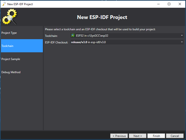
First, we'll need to create a project in Visual Studio with VisualGDB. This example is called myArduinoConversion:
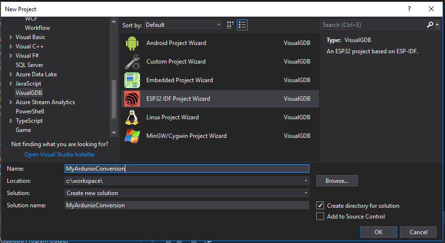
Leave default at "Create a new project based on a sample project". (hopefully the sysprogs folks will fix the black-on-dark-gray color scheme for those of of that choose the dark theme in Visual Studio):

If you don't have the ESP-IDF installed, there will be a prompt:
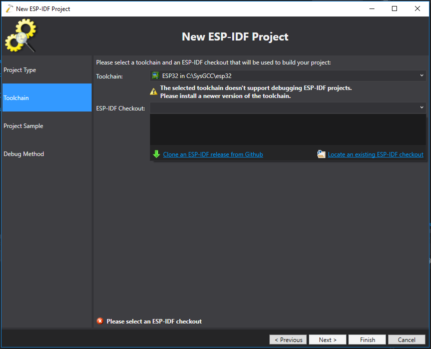
In my case, there was a version error. (despite the version warning, my C:\SysGCC\esp32\esp-idf\master-VisualGDB didn't even exist!
Click Clone an ESP-IDF from GitHub link to download:

VisualGDB may give an error:
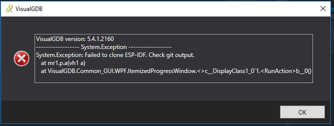
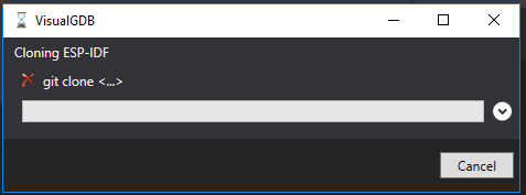
So I manually downloaded the toolchain. Unfortunately the error message does now show the actual command being attempted:
mkdir C:\SysGCC\esp32\esp-idf\master
cd C:\SysGCC\esp32\esp-idf\master
git clone --recursive https://github.com/espressif/esp-idf.git
Documents\Arduino\hardware\espressif\esp32C:\SysGCC\esp32\esp-idf\master\esp-idfNext, ensure the proper ESP32 toolchain is selected:
Next, choose a sample project. Here we use the get-started / blink template:

Next is the JTAG driver. In my case, I am using the ESP32-WROVER-KIT V3, and I chose the interface/ftdi/esp32-devkitj_v1,cfg file:

Here we can optionally press the "test" button, for a result like this if everything is working properly:

Although there's a "next" button there, it does not do anything; click "finish".
WAIT. (yes, it takes a surprisingly long time) It appears nothing is happening. I think most of the time is spent setting up the project ESP-IDF container. Eventually a new "blink.c" file shows up:
/* Blink Example
This example code is in the Public Domain (or CC0 licensed, at your option.)
Unless required by applicable law or agreed to in writing, this
software is distributed on an "AS IS" BASIS, WITHOUT WARRANTIES OR
CONDITIONS OF ANY KIND, either express or implied.
*/
#include <stdio.h>
#include "freertos/FreeRTOS.h"
#include "freertos/task.h"
#include "driver/gpio.h"
#include "sdkconfig.h"
/* Can run 'make menuconfig' to choose the GPIO to blink,
or you can edit the following line and set a number here.
*/
#define BLINK_GPIO CONFIG_BLINK_GPIO
void blink_task(void *pvParameter)
{
/* Configure the IOMUX register for pad BLINK_GPIO (some pads are
muxed to GPIO on reset already, but some default to other
functions and need to be switched to GPIO. Consult the
Technical Reference for a list of pads and their default
functions.)
*/
gpio_pad_select_gpio(BLINK_GPIO);
/* Set the GPIO as a push/pull output */
gpio_set_direction(BLINK_GPIO, GPIO_MODE_OUTPUT);
while(1) {
/* Blink off (output low) */
gpio_set_level(BLINK_GPIO, 0);
vTaskDelay(1000 / portTICK_PERIOD_MS);
/* Blink on (output high) */
gpio_set_level(BLINK_GPIO, 1);
vTaskDelay(1000 / portTICK_PERIOD_MS);
}
}
void app_main()
{
xTaskCreate(&blink_task, "blink_task", configMINIMAL_STACK_SIZE, NULL, 5, NULL);
}
The first thing we'll need to do is take that sketch_mmmdd.ino file and rename it to something like main.cpp and make a few other changes. (hopefully in a future release, sysprogs will give the option of using C or C++ sample templates).
In the case of this blink app, BLINK_GPIO is simply defined as "2" with no type. The
gpio_set_level expects a gpio_num_t like this: gpio_set_level(static_cast<gpio_num_t>(BLINK_GPIO), 0);The blink.c will also need to be renamed blink.cpp (apparently to ensure the compiler knows we are doing C++ and not just C). Preview 2 does not support right-click to rename, but you can click on the file in Solution Explorer and press F2 to enable the rename.
Only other minor tweak is needed; add
extern "C" before the void main() like this:
extern "C" void app_main()The revised code now looks like this:
/* Blink Example

   This example code is in the Public Domain (or CC0 licensed, at your option.)

   Unless required by applicable law or agreed to in writing, this
   software is distributed on an "AS IS" BASIS, WITHOUT WARRANTIES OR
   CONDITIONS OF ANY KIND, either express or implied.
*/
#include <stdio.h>
#include "freertos/FreeRTOS.h"
#include "freertos/task.h"
#include "driver/gpio.h"
#include "sdkconfig.h"

/* Can run 'make menuconfig' to choose the GPIO to blink,
   or you can edit the following line and set a number here.
*/
#define BLINK_GPIO 2

void blink_task(void *pvParameter)
{
    /* Configure the IOMUX register for pad BLINK_GPIO (some pads are
       muxed to GPIO on reset already, but some default to other
       functions and need to be switched to GPIO. Consult the
       Technical Reference for a list of pads and their default
       functions.)
    */
    gpio_pad_select_gpio(BLINK_GPIO);
    /* Set the GPIO as a push/pull output */
 gpio_set_direction(static_cast<gpio_num_t>(BLINK_GPIO), GPIO_MODE_OUTPUT);
    while(1) {
        /* Blink off (output low) */
     gpio_set_level(static_cast<gpio_num_t>(BLINK_GPIO), 0);
        vTaskDelay(1000 / portTICK_PERIOD_MS);
        /* Blink on (output high) */
     gpio_set_level(static_cast<gpio_num_t>(BLINK_GPIO), 1);
        vTaskDelay(1000 / portTICK_PERIOD_MS);
    }
}

extern "C" void app_main()
{
    xTaskCreate(&blink_task, "blink_task", configMINIMAL_STACK_SIZE, NULL, 5, NULL);
}
So that all is your basic VisualGDB project. Not a whole lot new. Yet.
I've been tinkering with LoRa stuff, and being able to single-step debug the code will be helpful. I'm using the RadioHead library and my local copy is git-cloned into \Documents\libraries\RadioHead. The interesting thing here is that the library is what I call "Arduino-style". I've never been able to get VisualGDB to play well with them, so I do a lot of development with VisualMicro instead. It is less expensive and fully supports the Arduino libraries. Alas I have a tons of "if debugging serial print" statements, as the JTAGsupport is weak. (there is however a VisualMicro GDB tutorial I've been meaning to check out). The reality is the sysprogs VisualGDB is simply a more extensive and robust implementation with JTAG support (with a price to show for it). The problem with the sysprogs folks however, is they never had much of an interest in Arduino. (Yes, I want my cake and JTAG it too!)
So a single include statement turns out project into something considerably more interesting.
#include "RH_RF95.h"
Actually we'll do a few more things to instantiate the RadioHead drivers:
#include "RH_RF95.h"

#define RFM95_CS 5   // LORA_CS_PIN
#define RFM95_RST 36 // LORA_RST_PIN is 36, TODO but it is read-only! so we'll need to short to another pin
#define RFM95_INT 26 // M5 LORA_IRQ_PIN 36 (jumper to 16)
RH_RF95 rf95(RFM95_CS, RFM95_INT);
Ok, so the code is actually from my M5Stack project, and I don't yet have LoRa hooked up to my lastest ESP32-WROVER, but that's beside the point...
After adding the code, the IDE will complain:

So simply go into Project-Properties and add the path the the "Additional Include Directories". In my case that's:
C:\Users\gojimmypi\Documents\Arduino\libraries\RadioHead
NOTE: If your cursor is in the source code panel when you click Project-Properties, you'll get this modal dialog box. It is NOT the one to use to enter paths for include files (it didn't work for me):

Be sure to click on the project name in the solution explorer, and THEN click Project - Properties:

...for this dialog box to enter the Additional Include File Directory paths:
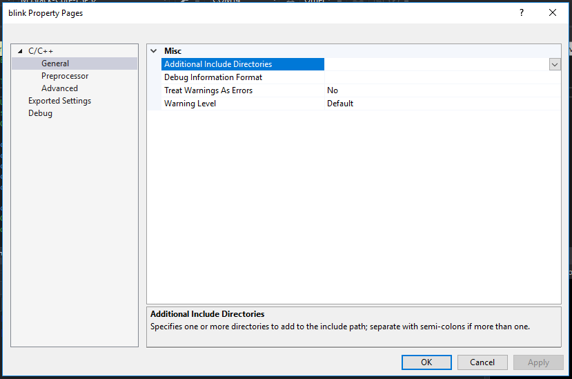
(note I like to make a habit of always pressing "Apply" before pressing ok, anytime that option is available)
That will take care of finding the code, but trying to compile will give an error about platform not defined:

The first compile will take some time. There's a shockingly large amount of code that gets compiled for such a tiny target. If when building/cleaning/rebuilding, nothing happens, simply exit Visual Studio and relaunch (see below).
This is another one of those Arduino-style nuances. You'll notice this code in RadioHead.h header and shown here:
#ifndef RH_PLATFORM
 #if (MPIDE>=150 && defined(ARDUINO))
  // Using ChipKIT Core on Arduino IDE
  #define RH_PLATFORM RH_PLATFORM_CHIPKIT_CORE
 #elif defined(MPIDE)
  // Uno32 under old MPIDE, which has been discontinued:
  #define RH_PLATFORM RH_PLATFORM_UNO32
#elif defined(NRF51)
  #define RH_PLATFORM RH_PLATFORM_NRF51
#elif defined(NRF52)
  #define RH_PLATFORM RH_PLATFORM_NRF52
 #elif defined(ESP8266)
  #define RH_PLATFORM RH_PLATFORM_ESP8266
 #elif defined(ESP32)
  #define RH_PLATFORM RH_PLATFORM_ESP32
 #elif defined(ARDUINO)
  #define RH_PLATFORM RH_PLATFORM_ARDUINO
 #elif defined(__MSP430G2452__) || defined(__MSP430G2553__)
  #define RH_PLATFORM RH_PLATFORM_MSP430
 #elif defined(MCU_STM32F103RE)
  #define RH_PLATFORM RH_PLATFORM_STM32
 #elif defined(STM32F2XX)
  #define RH_PLATFORM RH_PLATFORM_STM32F2
 #elif defined(USE_STDPERIPH_DRIVER)
  #define RH_PLATFORM RH_PLATFORM_STM32STD
 #elif defined(RASPBERRY_PI)
  #define RH_PLATFORM RH_PLATFORM_RASPI
#elif defined(__unix__) // Linux
  #define RH_PLATFORM RH_PLATFORM_UNIX
#elif defined(__APPLE__) // OSX
  #define RH_PLATFORM RH_PLATFORM_UNIX
 #else
  #error Platform not defined!
 #endif
#endif

#if defined(__AVR_ATtiny84__) || defined(__AVR_ATtiny85__) || defined(__AVR_ATtiny24__) || defined(__AVR_ATtiny44__) || defined(__AVR_ATtiny45__) || defined(__AVR_ATtinyX4__) || defined(__AVR_ATtinyX5__) || defined(__AVR_ATtiny2313__) || defined(__AVR_ATtiny4313__) || defined(__AVR_ATtinyX313__)
 #define RH_PLATFORM_ATTINY
#endif
To fix, simply add "ESP32" as a Preprocessor definition:

Rebuild again. There's a subtle change in the error message:
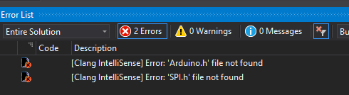
So this starts looking a bit more intimidating: Arduino.h missing for our ESP32 project. I took the brute-force approach and searched from the root of my C:\ drive:
C:
cd\
dir Arduino.h /s
I had a 32 matches in various locations. Some are obviously not of interest if found in an .\Arduino\ directory. In my case, I have the Espressif Arduino Core git-cloned in my .\Documents\Hardware\Espressif directory. It can be installed like this:
cd %USERPROFILE%\documents
mkdir hardware
git clone --recursive https://github.com/espressif/arduino-esp32.git
cd arduino-esp32
dir Arduino.h /s
dir SPI.h /s
dir pins_arduino.h /s
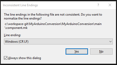
Put that directory in the include file list. Compile again and find another missing header file. Repeat. Note the pins_arduino.h is found in multiple directories. I chose the generic ESP32 one. After doing this a few times, VisualGDB often will complain the the settings are corrupt:

I simply exited Visual Studio and restarted. Upon restart, it complained out "line endings not being consistent". VisualGDB probably did this to itself; simple answer yes to fix:
Upon doing a rebuild, I found more files missing. Repeat the procedure for finding files.
Mine were found in:
C:\Users\gojimmypi\Documents\Arduino\libraries\RadioHead
C:\Users\gojimmypi\Documents\Arduino\hardware\espressif\esp32
C:\Users\gojimmypi\Documents\Arduino\hardware\espressif\esp32\cores\esp32
C:\Users\gojimmypi\Documents\Arduino\hardware\espressif\esp32\libraries\SPI\src
C:\Users\gojimmypi\Documents\Arduino\hardware\espressif\esp32\variants\esp32

May also need:
C:\Users\gojimmypi\Documents\Arduino\hardware\espressif\esp32\variants\doitESP32devkitV1
Note that the include file locations is not the only place for this fix; The intellisense will be happy, however the compiler does not seem to "find" there files. There is where things get a little wonky. Those same include files paths need to be added to the project. Right-click on the project, add, existing item (for each of the directories listed above).

Paste one of those include file paths into the File Name box. I choose to select header files (some directories have only headers!). Pick one of them. VisualGDB will recognize that there are others and prompt you to add them all. Click ok.
If multiple files are found, there will be a prompt asking if they all should be added (yes, they should):
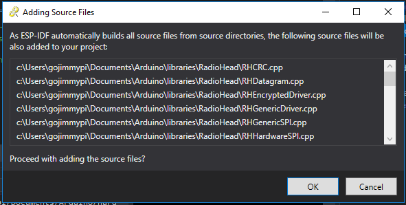
Rebuild the project. (sometimes it can help to clean, and then do a full rebuild).
Tada! A fully compiled Arduino-style library with VisualGDB. For me - this was really quite cool: something I've been wanting to do for a long time.

There are still a few weird things. The include files are presented in the Solution Explorer in a pretty bizarre fashion. As these same include directories are found in the Project Properties, I really think it would be best of the directory scanning and file additions happened transparently to the developer.

Also, It seems that breakpoint cannot be placed directly on those included files. However you can step-into them. Unfortunately the only option is step into. Step-over does not seem to work. Nor does step out. Alas this is only Preview 2, and still in development.
The Solution Explorer also looks a bit odd:

There's also some wonkiness with OpenOCD when code is paused too long. I think there's some sort of panic watchdog that is not fed while single-step debug is paused:

And no sooner do I polish this Preview 2 blog... the sysprogs folks have already released Preview 3! (And yes, it DOES appear to work in Preview 3 as well!)
* July 2018 edit:
Over the course of time, my Windows 10 drivers were changed, resulting in the dreaded message:
Error: libusb_open() failed with LIBUSB_ERROR_ACCESS
Error: no device found
Error: unable to open ftdi device with vid 0403, pid 6010, description '*', serial '*' at bus location '*'
Zadig to the rescue once again! Change both drivers on

I am using the config file found in:
That specifically looks like this:
Interface 0 and Interface 1 to libusbk.
I am using the config file found in:
C:\sysgcc\esp32\esp32-bsp\OpenOCD\share\openocd\scripts\interface\ftdi\esp32_devkitj_v1.cfgThat specifically looks like this:
#
# Driver for the FT2232H JTAG chip on the Espressif DevkitJ board
#


interface ftdi
ftdi_vid_pid 0x0403 0x6010

# interface 1 is the uart
ftdi_channel 0
# just TCK TDI TDO TMS, no reset
ftdi_layout_init 0x0008 0x000b
reset_config none


No comments:
Post a Comment
comments are disabled as nobody seemed to understand the no spam request.
See my latest blog at gojimmypi.github.io
Note: Only a member of this blog may post a comment.