Saturday, July 22, 2017

OpenWRT on EA3500 with RTL-SDR Stream

Recently I saw an interesting rtl-sdr article with a YouTube video on setting up a used Cicso LinkSys EA3500 router with OpenWrt and the RTL-SDR, (the second part of the video is here).

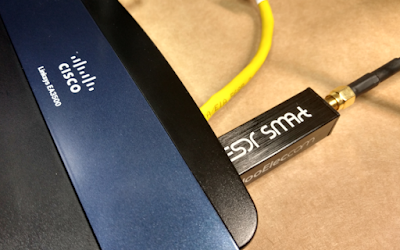
Cisco EA3500 with NooElec RTL-SDR
The video was so interesting, that I found a used EA3500 for sale on ebay and immediately purchased it to try this myself! (not a single one of my routers has a USB interface. Go figure) There are also used ones on amazon as well.

Although it was the topic of SDR caught my attention, it is still a pretty good video on OpenWrt.

The cool thing is that when done - I can move my RTL-SDR device anywhere within range of WiFi! Sweet. No longer limited to USB cable distance of my computer.

For stock firmware, there's no username; default password is admin

You should note that when the router first boots with stock firmware and factory reset, there's NO security on WiFi.

I did this on Windows 10, with the Ubuntu WSL for ssh access and other unix tools like iperf.

My wired test network is setup specifically to allow new devices with the default 192.168.1.1 address to work without having to unplug and re-plug my computer for many devices. However for this exercise I need to connect to OpenWrt before it is configured. So my setup is a little different than the video:


[internet] -- [switch: 192.168.1.x ] --- [yellow ES3500 Internet port]
                                         [blue ES3500 Ethernet port  ] --- [my computer]


While videos are cool, they make for poor reference material for later use. It is difficult to "scroll" though a video looking for a particular technical item. I'll keep track of all the details here.

The first reference is to the WikiDevi Linksys EA3500 page, with a link to the OpenWrt page for the Linksys EA3500. Despite the name factory.bin - this is NOT the stock Linksys software. This is the file to download for OpenWrt. There's more information on the Techdata: Linksys3500 page. That's where you can find a link to Firmware OpenWrt Install URL.

The first thing I did was brick my router. :(  I loaded that openwrt-kirkwood-linksys-audi-squashfs-factory.bin mentioned above. It did not go well. Fortunately there's a magic sequence of events to restore it. Thanks mikemccartney for posting these instructions that worked for me:


1 Plug in the EA3500/4500
2 Power led will blink rapidly
3 Power led will turn off
4 As soon as the power led turns off, unplug the router
5 Wait a few seconds
6 Plug the router back in and repeat the above process

Do that three times, on the fourth time keep the router plugged in and let it boot, hopefully you will now have a functioning router again.

I'm just glad I didn't have to figure out how to JTAG the firmware onto the router.

This time when loading openwrt-kirkwood-linksys-audi-squashfs-factory.bin things went much better.

So back to the video instructions: there's no default web UI when OpenWrt first boots. To initially access the new firmware, use: ssh root@192.168.1.1 and it should look something like this:


0 $ ssh root@192.168.1.1
The authenticity of host '192.168.1.1 (192.168.1.1)' can't be established.
RSA key fingerprint is 6e:6d:a4:4e:83:9e:54:10:b3:be:c0:76:bf:eb:aa:e3.
Are you sure you want to continue connecting (yes/no)? yes
Warning: Permanently added '192.168.1.1' (RSA) to the list of known hosts.


BusyBox v1.24.2 () built-in shell (ash)

  _______                     ________        __
 |       |.-----.-----.-----.|  |  |  |.----.|  |_
 |   -   ||  _  |  -__|     ||  |  |  ||   _||   _|
 |_______||   __|_____|__|__||________||__|  |____|
          |__| W I R E L E S S   F R E E D O M
 -----------------------------------------------------
 DESIGNATED DRIVER (Bleeding Edge, 50107)
 -----------------------------------------------------
  * 2 oz. Orange Juice         Combine all juices in a
  * 2 oz. Pineapple Juice      tall glass filled with
  * 2 oz. Grapefruit Juice     ice, stir well.
  * 2 oz. Cranberry Juice
 -----------------------------------------------------
root@OpenWrt:~#
Next set password with
passwd
command:
root@OpenWrt:~# passwd
Changing password for root
New password:
Retype password:
Password for root changed by root

If you are familar with VI/VIM you can skip this step, otherwise you can install nano:
opkg update

You may wish to save you original configs:
cp  /etc/config/network  /etc/config/network.bak
cp  /etc/config/wireless /etc/config/wireless.bak
Edit /etc/config/network that originally looks like this:
config interface 'loopback'
        option ifname 'lo'
        option proto 'static'
        option ipaddr '127.0.0.1'
        option netmask '255.0.0.0'

config globals 'globals'
        option ula_prefix 'fdbc:cc57:906d::/48'

config interface 'lan'
        option type 'bridge'
        option ifname 'eth0'
        option proto 'static'
        option ipaddr '192.168.1.1'
        option netmask '255.255.255.0'
        option ip6assign '60'

config interface 'wan'
        option ifname 'eth1'
        option proto 'dhcp'

config interface 'wan6'
        option ifname 'eth1'
        option proto 'dhcpv6'

config switch
        option name 'switch0'
        option reset '1'
        option enable_vlan '1'

config switch_vlan
        option device 'switch0'
        option vlan '1'
        option ports '0 1 2 3 5'

config switch_vlan
        option device 'switch0'
        option vlan '2'
        option ports '4 6'

He edits the network from 192.168.1.1 to 192.168.2.1
config interface 'lan'
        option ipaddr '192.168.2.1'
and changes the wan interface from eth1 to wlan0 for both.
config interface 'wan'
        option ifname 'wlan0'

config interface 'wan6'
        option ifname 'wlan0'

Then edit /etc/config/wireless that for a default config, that originally looks like this.
config wifi-device  radio0
        option type     mac80211
        option channel  11
        option hwmode   11g
        option path     'mbus/mbus:pcie-controller/pci0000:00/0000:00:01.0/0000:01:00.0'
        option htmode   HT20
        # REMOVE THIS LINE TO ENABLE WIFI:
        option disabled 1

config wifi-iface
        option device   radio0
        option network  lan
        option mode     ap
        option ssid     OpenWrt
        option encryption none

config wifi-device  radio1
        option type     mac80211
        option channel  36
        option hwmode   11a
        option path     'mbus/mbus:pcie-controller/pci0000:00/0000:00:02.0/0000:02:00.0'
        option htmode   HT20
        # REMOVE THIS LINE TO ENABLE WIFI:
        option disabled 1

config wifi-iface
        option device   radio1
        option network  lan
        option mode     ap
        option ssid     OpenWrt
        option encryption none

Remove the channel selection and enable wifi (by setting disabled to false):
config wifi-device  radio0
        # option channel  11
        option disabled 0
And edit the wifi-iface section for 2GHz:
config wifi-iface
        option device   radio0
        option network  wan
        option mode     sta
        option ssid     yourssid
        option encryption psk2
        option key      yourwifipassword
Edit the wifi-iface section for 5GHz in a similar manner if you have one (I do not). The reboot, wait, and ssh to the NEW IP address:
reboot;exit
# wait...
ssh root@192.168.2.1
Once everything is configured, the cable between the yellow Ethernet port and the switch can be removed, as the router is now a station

[internet] -- [WiFi (same as above switched network)]   
                            [WiFi]  ---- [blue ES3500 Ethernet port  ] --- [my computer]
Other things installed in the video include installing LuCI (the graphical web gui). Note the video installed regular luci; I prefer the luci-ssl, even though the browser will complain that it is not a secure connection (no trusted root for self-signed cert)


opkg update
# opkg install luci # the non-ssl version
opkg install luci-ssl
/etc/init.d/uhttpd start
/etc/init.d/uhttpd enable
Then see which RTL packages are available:
opkg list | grep rtl
He then goes on to install rtl-sdr
opkg install rtl-sdr
which rtl_fm
which rtl_tcp
rtl_tcp -h
Plugging in my NooElec RTL-SDR that I received for Christmas (what a cool gift!!) I see this latest entry with dmesg:
[ 2819.934581] usb 1-1: new high-speed USB device number 2 using orion-ehci
Then simply run rtl_tcp:
root@OpenWrt:~# rtl_tcp
Found 1 device(s):
  0:  Realtek, RTL2838UHIDIR, SN: 00000001

Using device 0: Generic RTL2832U OEM
Found Rafael Micro R820T tuner
[R82XX] PLL not locked!
Tuned to 100000000 Hz.
listening...
Use the device argument 'rtl_tcp=127.0.0.1:1234' in OsmoSDR (gr-osmosdr) source
to receive samples in GRC and control rtl_tcp parameters (frequency, gain, ...).
Other things installs in the video:

 
opkg list | grep dump
opkg install dump1090
opkg install iperf
Part two of the video starts out a bit confusing... but skip the first 7 minutes and pick up at the OpenWrt login prompt. There's a reminder on restarting WiFi:

wifi down; wifi up
# or
ifconfig wlan0 down
ifconfig wlan0 up

Basically to ensure there's an IP address listed for wlan0. (the client DHCP address for your WiFi network; remember this device was configured as STA, not AP (above).
As such, the ES3500 is connected to the "internet" via WiFi instead of via the yellow RJ-45 connector. Thus for wireless access, port forwarding is needed. At first, I setup a simple traffic rule that worked:


However I wanted to follow along and use port forwarding instead, like this:

A port forward that looks like it should work, but does not.

Unfortunately, the video already had many of the port forwards already configured. I had a difficult time with getting ssh working. I kept getting these odd connection refused errors:
gojimmypi@ElectronicsDesk : ~
255 $ ssh root@192.168.1.131
ssh: connect to host 192.168.1.131 port 22: Connection refused
Now "connection refused" is an interesting error. It says things are working but being rejected. I was sure I had it configured correctly. As it turns out there's a feature specifically to allow ssh under System - Administration:


Even setting the "allow remote hosts", I continued to get the port refusal error. So in the video, he connects to the client STA address of the EA3500. Yet when on the local 192.168.2.x network, I was ssh'ing into the router IP address: 192.168.2.1 and not its client STA address of 192.168.1.131 - so I used that as a port forward instead. Note that it shows up in the drop-down as "(Openwrt,lan)" next to the IP addy


And so once that is working, several other ports also need to be forwarded:

Note that when moving your client computer between the ES3500 network (192.168.2.x) and the local wired/wireless network (192.168.1.x) - there's a delay of up to several minutes in Windows obtaining the new address and getting everything setup, during which you'll see messages like this when attempting ssh:


ssh: connect to host 192.168.1.131 port 22: Software caused connection abort
ssh: connect to host 192.168.1.131 port 22: Resource temporarily unavailable
ssh: connect to host 192.168.1.131 port 22: Network is unreachable

If you still have problems connecting, recheck settings and try reboot. But be patient, it does take some time. Again, note that I believe the port forwards in the video are completely wrong - and the only reason he was able to get it working was the traffic rules. I have no traffic rules - just the port forwards, but to a different address. But then again, I spent the better part of the afternoon playing with this - and the video author sped though the entire process in an impressive 37 minutes apparently with no editing / interruptions. Impressive.
Once that is working, I setup iperf as a server on the EA3500:
iperf -s
In a separate shell, staying local the PC (I also needed to install iperf):
sudo apt-get install iperf
iperf -c 192.168.1.131 -i 3 -t 30
and saw mediocre performance from this "gigabit" router:

------------------------------------------------------------
Client connecting to 192.168.1.131, TCP port 5001
TCP window size:  512 KByte (default)
------------------------------------------------------------
[  3] local 192.168.1.143 port 5607 connected with 192.168.1.131 port 5001
[ ID] Interval       Transfer     Bandwidth
[  3]  0.0- 3.0 sec  6.75 MBytes  18.9 Mbits/sec
[  3]  3.0- 6.0 sec  8.00 MBytes  22.4 Mbits/sec
[  3]  6.0- 9.0 sec  7.12 MBytes  19.9 Mbits/sec
[  3]  9.0-12.0 sec  7.75 MBytes  21.7 Mbits/sec
[  3] 12.0-15.0 sec  7.38 MBytes  20.6 Mbits/sec
[  3] 15.0-18.0 sec  7.25 MBytes  20.3 Mbits/sec
[  3] 18.0-21.0 sec  7.88 MBytes  22.0 Mbits/sec
[  3] 21.0-24.0 sec  7.62 MBytes  21.3 Mbits/sec
[  3] 24.0-27.0 sec  7.75 MBytes  21.7 Mbits/sec
[  3] 27.0-30.0 sec  7.88 MBytes  22.0 Mbits/sec
[  3]  0.0-30.1 sec  75.5 MBytes  21.1 Mbits/sec
Note that Norton Antivirus popped up and warned about the iperf traffic; the default recommended action was to block it. Your AV may simply quietly block it. So if ssh and the web interface are working but not iperf; check your antivirus software. YMMV.

The video moves on to trying performance with a 5GHz band. I don't have any other 5GHz routers, so I could not test this. Important thing to note is that he ended up apparently needed to power cycle the router when changing from 2.5GHx to 5GHz.

So on to SDR "Sharp" (which was also already install in the video). You can download the AirSpy SDR# here. Norton AV gave me a ton of grief on many of the SDR# executables. Here's the config in SDR#. The only thing is setting the IP address for RTL-SDR (tcp):


Although the original pic above has the RTL-SDR plugged directly into the router, it is probably a good idea to use an extension cord, as shown in the video to get the receiver a bit farther away.

Note that we are port forwarding the br-lan address: 192.168.2.1 from the 192.168.1.x network. Thus we need to tell rtl_tcp to listen on that address:

rtl_tcp -a 192.168.2.1 -f 95300000
Press play button in SDR# and voila!


Resources, Inspiration, Credits, and Other Links:


Sunday, July 16, 2017

Updating adafruit.io ESP8266 MQTT code

While working on my flow and pressure project, I stumbled upon a notice that Adafruit planned to change the SSL info for adafruit.io. I had been using this (beta) site for mqtt telemetry. And so today... sure enough: my code is broken & no longer connecting.


I was hoping it was a simple matter of updating the SSL fingerprint to a new value.

const char* fingerprint = "26 96 1C 2A 51 07 FD 15 80 96 93 AE F7 32 CE B9 0D 01 55 C4";
No luck there, as the fingerprint did not change - but the declarative name did. <sigh> Well, so the github repository is here. But I have been blissfully ignorant of exactly where everything is stored. A mixed blessing in allowing me focusing on my code, but sometimes scary in not knowing how everything works. Alas no-one can know everything. So back to the ESP8266 crutch: The Arduino IDE! Click Sketch - Include Library - Manage Libraries. (it is the top-most menu item). Find the installed adafruit mqtt library and click update!


If like me - you are using VisualMicro, I believe it is usually best to exit and restart Visual Studio.


It didn't work. Not only does the connection still fail, but the needed code was apparently not actually updated (the drawback of hiding libraries in a GUI). I know it is not working as the new fingerprint is defined with AIO_SSL_FINGERPRINT and the old one with fingerprint, and there's no compile error without the AIO_SSL_FINGERPRINT. So ya, there appears to be a new include file: adafruitio_definition. I have no such file on my entire system. Well, seems that the Arduino IDE was not successful in getting the really latest adafruit mqtt library.
So the issue here is more than the MQTT library... I also needed to update the Adafruit Arduino IO (listed immediately above in the screen snip). Again exit / restart Visual Studio.

Next, I saw this error:
AdafruitIO.h: 22:31: fatal error: ArduinoHttpClient.h: No such file or directory
   #include "ArduinoHttpClient.h"
   compilation terminated
Seems that the latest Adafruit MQTT also needs the new (apparently experimental at this time) ArduinoHttpClient library. So I installed that from Arduino IDE as well. And restarted Visual Studio. So ya, just as described here. (once you kow that the Arduino IO library is required by new new MQTT.

Ok, so now what? The github repository sample code for adafruitio secure esp8266 is still from last year. No tweets from adafruitio. No other messages on the forum. Blog apparently has "major outage".


End of story for today on this topic. Hopefully more documentation and examples will be available soon.

Saturday, July 15, 2017

ESP8266 OTA Water Pressure Flow Monitor

I've been working with the ESP8266 for quite some time now, but I've only programmed it while it was sitting right at my desk and having it plugged into a USB port. A variety of projects that I have developed have always been convenient to test. However my latest creation involves water. I could not quite imagine how I'd test this at my workbench, nor did it seem very appealing to be programming in the garage. In the summer. In California.

Today I discovered how amazingly simply it is to do "Over The Air" (OTA) programming of the ESP8266, thanks to this really cool Random Nerd Tutorial - ESP8266 OTA Updates with Arduino IDE | Over the Air.

I've been wanting to hook up these pressure and flow sensors that I found on ebay to monitor water usage. I also needed a few fittings that I found on Amazon. I purchased there as I could return them free, no hassle if there was a problem; I had a dreadful time finding anything like this at the local hardware store. I needed this Stainless Steel 316 Cast Pipe Fitting, Hex Bushing, MSS SP-114, 3/4" X 1/4" NPT Male X Female adapter for the pressure sensor, and thisStainless Steel 316 Cast Pipe Fitting, Tee, Class 150, 3/4" NPT Female so that I could hook up both the pressure sensor and flow meter at the same time. The result is a male-female connector that I can slip inline.


You may wonder why I would be interested in something as boring as water pressure. Well, not long ago I discovered my pressure regulator quietly failed. Let's just say I will never again ignore water pressure! There's a reason for the regulator - and the maximum ratings on the water heater. The water softener. The reverse osmosis system.... For only about 10 bucks, you can keep an eye on pressure the  manual, old-school way with this Rain Bird P2A Water Pressure Test Gauge - but what fun is that when there's an electronic gizmo option?

I admit I had some temporary disappointment at the beginning of Step 3 of the OTA tutorial, where I expected to see the the esp8266-xxxxxx at my_esp_ip_address port. I did not. I was not able to see this until exiting and restarting Arduino. No worries, onward!

The next step is to program in some other environment other than the Arduino IDE. I am quite addicted to Visual Studio. I have both the VisualGDB and VisualMicro add-ins. I like VisualMicro in that I can take Arduino code samples and immediately start coding. I have yet to figure out how to do this with VisualGDB. The last time I asked about it, there was no hope on the horizon for Arduino support in VisualGDB,

Initially, it appears there's no option other than the Arduino IDE to actually program OTA. I could find nothing in Visual Studio where it could "see" the pseudo-serial-over-ethernet port. Ha! But fortunately there's a verbose output from the Arduino IDE. In particular this last command shown before uploading:

python.exe C:\Users\gojimmypi\AppData\Local\Arduino15\packages\esp8266\hardware\esp8266\2.3.0/tools/espota.py -i 192.168.1.103 -p 8266 --auth= -f C:\Users\GOJIMM~1\AppData\Local\Temp\arduino_build_690448/sketch_jul15a.ino.bin

The important thing here is that there's a python script called espota.py that sends a binary file to the OTA client. (side note: simply genius implementation in less than 9K!) The paths are crazy long, but the command is essentially this:

python.exe espota.py -i 192.168.1.101 -p 8266 --auth= -f yourfile.bin
Pasting the same OTA sample code into a VisualMicro Ardino Project in Visual Studio... then compiling, shows the output path of the binary:
"C:\Users\gojimmypi\AppData\Local\arduino15\packages\esp8266\tools\esptool\0.4.9/esptool.exe" -eo "C:\Users\gojimmypi\AppData\Local\arduino15\packages\esp8266\hardware\esp8266\2.3.0/bootloaders/eboot/eboot.elf" -bo "C:\Users\gojimmypi\AppData\Local\Temp\VMBuilds\WaterPressureFlow\esp8266_generic\Release/WaterPressureFlow.ino.bin" -bm qio -bf 40 -bz 4M -bs .text -bp 4096 -ec -eo "C:\Users\gojimmypi\AppData\Local\Temp\VMBuilds\WaterPressureFlow\esp8266_generic\Release/WaterPressureFlow.ino.elf" -bs .irom0.text -bs .text -bs .data -bs .rodata -bc -ec
This one is an even longer and crazier command. Really the only thing we are interested in is where the output file is stored. In my case it is:
"C:\Users\gojimmypi\AppData\Local\Temp\VMBuilds\WaterPressureFlow\esp8266_generic\Release/WaterPressureFlow.ino.bin"
There's some sloppy use of mixing forward and back-slashes; for Windows I highly recommend editing them and making them all backslashes.

So now using the Arduino OTA command with the destination of the VisualStudio binary, we can develop OTA with Visual Studio! My command looks like this:
python.exe C:\Users\gojimmypi\AppData\Local\Arduino15\packages\esp8266\hardware\esp8266\2.3.0\tools\espota.py -i 192.168.1.103 -p 8266 --auth= -f C:\Users\gojimmypi\AppData\Local\Temp\VMBuilds\WaterPressureFlow\esp8266_generic\Release\WaterPressureFlow.ino.bin
I thought perhaps this could be fully automated by adding the command to the Post Build Event in VisualStudio:
 
However I was unable to get the command to trigger. This article on Specifying Build Events at Microsoft seems to indicate that last option "In Excluded From Build, specify Yes if you do not want the event to run". However my prompt is "Use in Build". I tried both Yes and No - and the OTA command appears to never have been attempted. Perhaps this is because it is a VisualMicro project. No worries, still just as easy to use the up-arrow in a DOS box to re-upload freshly compiled code.

I'm still hopeful that I will be able to do this in a single build operation. The VisualMicro site has a page indicating that build events are now supported. I've submitted a question to their support forum to find out. It appears the only option is a "quite convoluted and difficult to test" option. Hopefully they have the built-in events working.
And indeed YES! Just minutes after posting my question on the forum, I received a response! A simple matter of right-click on project - add - Add Local Board.txt with this text

# WaterPressureFlow build property overrides
#
# local project board.txt overrides
network.port=8266
as described here. So no need for a convoluted solution or manual specification of build event. It just works! Be sure to press "enter" when entering an IP address for serial port (otherwise it won't stick). Now the VisualMicro "Build & Upload" sends OTA data. Sweet. :)


See also: https://github.com/gojimmypi/mqttFlowESP8266 and Updating adafruit.io ESP8266 MQTT code


Tuesday, July 4, 2017

Converting a Blue Pill STM32F103 board to a Black Magic Probe

Recently, I learned about the really awesome Black Magic Probe - an interesting JTAG and SWD adapter that essentially has its own, built-in OpenOCD server... so you can use only the GDB client to connect directly to this device for debugging! I've been meaning to place an order for one, but then I ran across this article that converts an STM32F103 "Blue Pill" board to a Black Magic Probe!

Edit: I also tried to use the Maple Mini clone, like this one unsuccessfully; Although I was able to flash the bootloader, my computer did not recognized the device when plugged into the mini-USB connector. (apparently I'm not the only one that was unsuccessful with this).

The instructions there appear very straightforward, however as soon as I saw the some of the text, I realized the guy was using a slightly different distro of linux. So I'll add my notes on using Ubuntu. My Ubuntu is in a VMWare Workstation Virtual Machine running on Windows 10. If you have a similar setup - just don't forget to connect the device as needed from host in VM - Removable Devices. The WSL Ubuntu on Windows that I have still does not yet recognize all USB devices.

Another significant issue for me turned out to the fact that the STM32F103C8T6 is (debatable: see my comment here and noted by someone else here) only a 64K device (8K for bootloader leaving 56K for app)... and the Black Magic Probe now compiles to 57K. If it was easy, it would be no fun, eh?

To get started, ensure the tool chain is installed:


sudo apt-get update
sudo apt-get install git --assume-yes
sudo apt-get install gcc-arm-none-eabi --assume-yes
sudo apt-get install dfu-util --assume-yes

cd ~/
mkdir -p workspace
cd ~/workspace/
git clone https://github.com/jsnyder/stm32loader.git # download stm32loader
git clone --recursive https://github.com/blacksphere/blackmagic.git # download Black Magic source
#git clone --recursive https://github.com/rogerclarkmelbourne/Arduino_STM32.git # optional, has stm32flash
# optional stm32flash (64 bit version)
mkdir -p tools
cd tools
wget https://github.com/rogerclarkmelbourne/Arduino_STM32/raw/master/tools/linux64/stm32flash/stm32flash
chmod +x stm32flash
cd ~/workspace/blackmagic
make
cd src
make clean && make PROBE_HOST=stlink


when all looks good, see if you can talk to your board:

sudo apt-get install python-serial
sudo chmod 777  /dev/ttyUSB0
cd ~/workspace/blackmagic/src/
python ~/workspace/stm32loader/stm32loader.py -p /dev/ttyUSB0

it should return a result like this:
Bootloader version 22
Chip id: 0x410 (STM32 Medium-density)

Ready to flash! However - note that this is where my instructions are different.

cd ~/workspace/blackmagic/src/
python ~/workspace/stm32loader/stm32loader.py -p /dev/ttyUSB0 -e -w -v blackmagic_dfu.bin

The first time I tried, there was an error (also not the jumper setting needed for BOOT0=1:
Can't init. Ensure that BOOT0 is enabled and reset device
Traceback (most recent call last):
  File "/home/gojimmypi/workspace/stm32loader/stm32loader.py", line 436, in 
    bootversion = cmd.cmdGet()
  File "/home/gojimmypi/workspace/stm32loader/stm32loader.py", line 118, in cmdGet
    if self.cmdGeneric(0x00):
  File "/home/gojimmypi/workspace/stm32loader/stm32loader.py", line 115, in cmdGeneric
    return self._wait_for_ask(hex(cmd))
  File "/home/gojimmypi/workspace/stm32loader/stm32loader.py", line 88, in _wait_for_ask
    raise CmdException("NACK "+info)
__main__.CmdException: NACK 0x0
So just as the error hint said, I pressed the reset button and tried again. Success! Output looks like this:
Bootloader version 22
Chip id: 0x410 (STM32 Medium-density)
Write 256 bytes at 0x8000000
Write 256 bytes at 0x8000100
  [..snip..]
Write 256 bytes at 0x8001900
Write 256 bytes at 0x8001A00
Read 256 bytes at 0x8000000
Read 256 bytes at 0x8000100
  [..snip..]
Read 256 bytes at 0x8001900
Read 256 bytes at 0x8001A00
Verification OK
DFU loader done! Be sure to move jumpers back to default of "0" and press reset again. The instructions that I followed indicated that the USB device should be disconnected and reconnected. Not much interesting or different there upon re-insertion. Device is still a cp2104 on /dev/ttyUSB0
[927124.098974] usb 2-2.1: new full-speed USB device number 18 using uhci_hcd
[927124.418782] usb 2-2.1: New USB device found, idVendor=10c4, idProduct=ea60
[927124.418783] usb 2-2.1: New USB device strings: Mfr=1, Product=2, SerialNumber=3
[927124.418784] usb 2-2.1: Product: CP2104 USB to UART Bridge Controller
[927124.418785] usb 2-2.1: Manufacturer: Silicon Labs
[927124.418786] usb 2-2.1: SerialNumber: 012345678
[927124.424936] cp210x 2-2.1:1.0: cp210x converter detected
[927124.433135] usb 2-2.1: cp210x converter now attached to ttyUSB0 
The first time I ran dfu-util:
dfu-util -d 1d50:6018,:6017 -s 0x08002000:leave -D blackmagic.bin
I received an error:
dfu-util 0.8

Copyright 2005-2009 Weston Schmidt, Harald Welte and OpenMoko Inc.
Copyright 2010-2014 Tormod Volden and Stefan Schmidt
This program is Free Software and has ABSOLUTELY NO WARRANTY
Please report bugs to dfu-util@lists.gnumonks.org

dfu-util: Invalid DFU suffix signature
dfu-util: A valid DFU suffix will be required in a future dfu-util release!!!
dfu-util: No DFU capable USB device available
I had 2 new devices: /dev/serial and /dev/ttyUSB0 when plugged in.

The reason for the error? I missed the MOST IMPORTANT PART:

Disconnect everything and use the USB to connect.

The Black Magic probe uses the micro USB connector, NOT the Serial TTL! (oops) Sure enough, the device is now listed in Device Manager:


A word of caution here: if you happen to use different sources of power, beware of ground loops. I highly recommend only 1 source of power (either the USB TTY/UART or onboard Micro USB. This could be particularly important if they are on different physical computers, using a USB hub, etc.

When you remove the TTY/UART and connect the USB port on the Blue Pill, you should see something like this with dmesg:

[937218.226791] usb 2-2.1: USB disconnect, device number 22
[937218.227053] cp210x ttyUSB0: cp210x converter now disconnected from ttyUSB0
[937218.227064] cp210x 2-2.1:1.0: device disconnected
[937223.643635] usb 2-2.1: new full-speed USB device number 23 using uhci_hcd
[937223.959267] usb 2-2.1: New USB device found, idVendor=10c4, idProduct=ea60
[937223.959269] usb 2-2.1: New USB device strings: Mfr=1, Product=2, SerialNumber=3
[937223.959271] usb 2-2.1: Product: CP2104 USB to UART Bridge Controller
[937223.959272] usb 2-2.1: Manufacturer: Silicon Labs
[937223.959273] usb 2-2.1: SerialNumber: 01234567
[937223.967154] cp210x 2-2.1:1.0: cp210x converter detected
[937223.973711] usb 2-2.1: cp210x converter now attached to ttyUSB0
[937258.140246] usb 2-2.1: USB disconnect, device number 23
[937258.144289] cp210x ttyUSB0: cp210x converter now disconnected from ttyUSB0
[937258.144327] cp210x 2-2.1:1.0: device disconnected

[938012.539892] usb 2-2.1: new full-speed USB device number 24 using uhci_hcd
[938012.886453] usb 2-2.1: New USB device found, idVendor=1d50, idProduct=6017
[938012.886455] usb 2-2.1: New USB device strings: Mfr=1, Product=2, SerialNumber=3
[938012.886472] usb 2-2.1: Product: Black Magic (Upgrade) for STLink/Discovery, (Firmware v1.6.1-43-g984f8b3)
[938012.886474] usb 2-2.1: Manufacturer: Black Sphere Technologies
[938012.886474] usb 2-2.1: SerialNumber: 76543210
Unfortunately dfu-util -l is not happy:

dfu-util 0.8

Copyright 2005-2009 Weston Schmidt, Harald Welte and OpenMoko Inc.
Copyright 2010-2014 Tormod Volden and Stefan Schmidt
This program is Free Software and has ABSOLUTELY NO WARRANTY
Please report bugs to dfu-util@lists.gnumonks.org

dfu-util: Cannot open DFU device 1d50:6017
To confirm the device is there,lsusb shows the device as "OpenMoko":

Bus 001 Device 001: ID 1d6b:0002 Linux Foundation 2.0 root hub
Bus 002 Device 025: ID 1d50:6017 OpenMoko, Inc.
Bus 002 Device 003: ID 0e0f:0002 VMware, Inc. Virtual USB Hub
Bus 002 Device 002: ID 0e0f:0003 VMware, Inc. Virtual Mouse
Bus 002 Device 001: ID 1d6b:0001 Linux Foundation 1.1 root hub
You can also view just the device you are looking for with the -d parameter:
lsusb -d 1d50:
(don't forget the trailing colon ":"!

Ok, not obvious - but the problem here is one again permissions. So run the command with sudo:

sudo dfu-util -l
If successful, the output should look like this:

dfu-util 0.8

Copyright 2005-2009 Weston Schmidt, Harald Welte and OpenMoko Inc.
Copyright 2010-2014 Tormod Volden and Stefan Schmidt
This program is Free Software and has ABSOLUTELY NO WARRANTY
Please report bugs to dfu-util@lists.gnumonks.org

Found DFU: [1d50:6017] ver=0100, devnum=27, cfg=1, intf=0, alt=0, name="@Internal Flash /0x08000000/8*001Ka,056*001Kg", serial="76543210"


Once you can see the device, run dfu-util with sudo:


sudo dfu-util -d 1d50:6018,:6017 -s 0x08002000:leave -D blackmagic.bin
I received an error, that sure looks like an out of memory issue:

dfu-util 0.8

Copyright 2005-2009 Weston Schmidt, Harald Welte and OpenMoko Inc.
Copyright 2010-2014 Tormod Volden and Stefan Schmidt
This program is Free Software and has ABSOLUTELY NO WARRANTY
Please report bugs to dfu-util@lists.gnumonks.org

dfu-util: Invalid DFU suffix signature
dfu-util: A valid DFU suffix will be required in a future dfu-util release!!!
Opening DFU capable USB device...
ID 1d50:6017
Run-time device DFU version 011a
Claiming USB DFU Interface...
Setting Alternate Setting #0 ...
Determining device status: state = dfuIDLE, status = 0
dfuIDLE, continuing
DFU mode device DFU version 011a
Device returned transfer size 1024
DfuSe interface name: "Internal Flash   "
Downloading to address = 0x08002000, size = 58364
dfu-util: Last page at 0x080103fb is not writeable
So I found other instructions relating to STM Discovery as a Black Magic Probe that indicated dfu_upgrade.bin needed to be loaded (I was willing to try anything!)

sudo dfu-util -d 1d50:6018,:6017 -s 0x08002000:leave -D dfu_upgrade.bin
The results are a bit more promising:

dfu-util 0.8

Copyright 2005-2009 Weston Schmidt, Harald Welte and OpenMoko Inc.
Copyright 2010-2014 Tormod Volden and Stefan Schmidt
This program is Free Software and has ABSOLUTELY NO WARRANTY
Please report bugs to dfu-util@lists.gnumonks.org

dfu-util: Invalid DFU suffix signature
dfu-util: A valid DFU suffix will be required in a future dfu-util release!!!
Opening DFU capable USB device...
ID 1d50:6017
Run-time device DFU version 011a
Claiming USB DFU Interface...
Setting Alternate Setting #0 ...
Determining device status: state = dfuIDLE, status = 0
dfuIDLE, continuing
DFU mode device DFU version 011a
Device returned transfer size 1024
DfuSe interface name: "Internal Flash   "
Downloading to address = 0x08002000, size = 6764
Download        [=========================] 100%         6764 bytes
Download done.
File downloaded successfully
Transitioning to dfuMANIFEST state
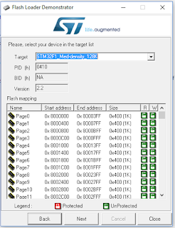
But even with that - I was completely unable to use dfu-util to program the Blue Pill with a 57K blackmagic.bin file. Even after power cycle, reset, etc. So I put the board back into USART programming mode (BOOT0 jumper=1, BOOT1 jumper=0) and used the ST Flash Loader app on Windows. The device is initially detected as a 65K device:


However on the next screen, apparently you can force it into 128K mode:


The select the blackmagic.bin file, click the "Erase necessary pages", select an address of 0x8002000 and check the "Verify after download" checkbox:


If successful, you should see:

I should point out that several times I received a verify error at this last verify step (I was really convinced I had a 64K-only device). After trying again the next day - things started working immediately and I never again saw the verify error, even after doing a full erase and starting over. YMMV.

Keep in mind that the fact that we are using 128K on a 64K device is rather dangerous. In all likelihood, the manufacturer does an exhaustive memory test: throws away the ones with an error in the first 64K, market the ones with an error in the second 64K as only a 64K STM32f103C8T6 device, and label the ones with no error as 128K STM32f103CBT6 devices. Although this may be a fun Saturday afternoon project, if you are serious about actually using and depending on a BlackMagic probe for real debugging, consider buying one. (besides, always good to support the developer).  When you are elbows-deep in debugging your own project, you really don't want a questionable debugger.

So at this point, I'm not even sure the dfu bootloader is needed, if we are loading the blackmagic.bin file this way.

My particular debugging experiment uses the STM Smart V2 board as a target, and using my STM32 to ST7735 TFT LCD display example with the source on github. This is somewhat of a convoluted setup, as the project is in Visual Studio 2017 (on Windows 10) with the VisualGDB Extension from Sysprogs.

As previously mentioned, I'm running my Ubuntu in a VM, and I have samba installed so that on Windows I can map a drive  (C$ is root  /):

net use z: \\192.168.1.30\c$ /user:gojimmypi

Debugging connections from Blue Pill board configured as a Black Magic Probe (micro usb connected to Ubuntu):

Connecting the Blue Pill Black Magic Probe to an STM Smart V2 board:


cd  ~/workspace
git clone https://github.com/gojimmypi/STM32-ST7735.git

then open the solution Z:\home\gojimmypi\workspace\STM32-ST7735\STM32-ST7735.sln in Visual Studio and compile.


cd  ~/workspace/STM32-ST7735/STM32-ST7735
arm-none-eabi-gdb -d ./ -f ~/workspace/STM32-ST7735/VisualGDB/Debug/STM32-ST7735 -tui
ls /dev/ttyACM* -al

then in GDB, connect with the first ttyACM[n] device (the second one is a serial port). Mine were originally ttyACM0 and ttyACM1, but then later changed to ttyACM1 and ttyACM2 (no idea how/why). I even saw an instance while debugging that ttyACM1 changed to ttyACM0 yes leaving me with (ttyACM0 and ttyACM2).Weird.
Anyhow, here are some useful GDB commands to get started:

target extended-remote /dev/ttyACM1
monitor swdp_scan
attach 1


If successful you should see something like this:

GNU gdb (7.10-1ubuntu3+9) 7.10
Copyright (C) 2015 Free Software Foundation, Inc.
License GPLv3+: GNU GPL version 3 or later 
This is free software: you are free to change and redistribute it.
There is NO WARRANTY, to the extent permitted by law.  Type "show copying"
and "show warranty" for details.
This GDB was configured as "--host=x86_64-linux-gnu --target=arm-none-eabi".
Type "show configuration" for configuration details.
For bug reporting instructions, please see:
.
Find the GDB manual and other documentation resources online at:
.
For help, type "help".
Type "apropos word" to search for commands related to "word"...
Reading symbols from /home/gojimmypi/workspace/STM32-ST7735/VisualGDB/Debug/STM32-ST7735...done.
(gdb) target extended-remote /dev/ttyACM1
Remote debugging using /dev/ttyACM1
(gdb) monitor swdp_scan
Target voltage: unknown
Available Targets:
No. Att Driver
 1      STM32F1 medium density
(gdb) attach 1
Attaching to program: /home/gojimmypi/workspace/STM32-ST7735/VisualGDB/Debug/STM32-ST7735, Remote target
0x08001514 in SetSysClockTo72 () at system_stm32f10x.c:993
(gdb)

sample


Resources, Inspiration, Credits, and Other Links:


Find gojimmypi at gojimmypi.github.io

I'm currently working on my new blog home at  gojimmypi.github.io After implementing a variety of features such as dark mode , syntax hi...