Monday, October 12, 2020

CNC 3018 Makerbot Limit Switch Wiring

This is a continuation of my prior blog on limit switch mounting hardware design for the CNC3018.

There are plenty of resources on various limit switch wiring. As with most information on the internet: some is good, some not so good. One place to start for the desktop CNC is the gnea/grbl wiki: Wiring Limit Switches.

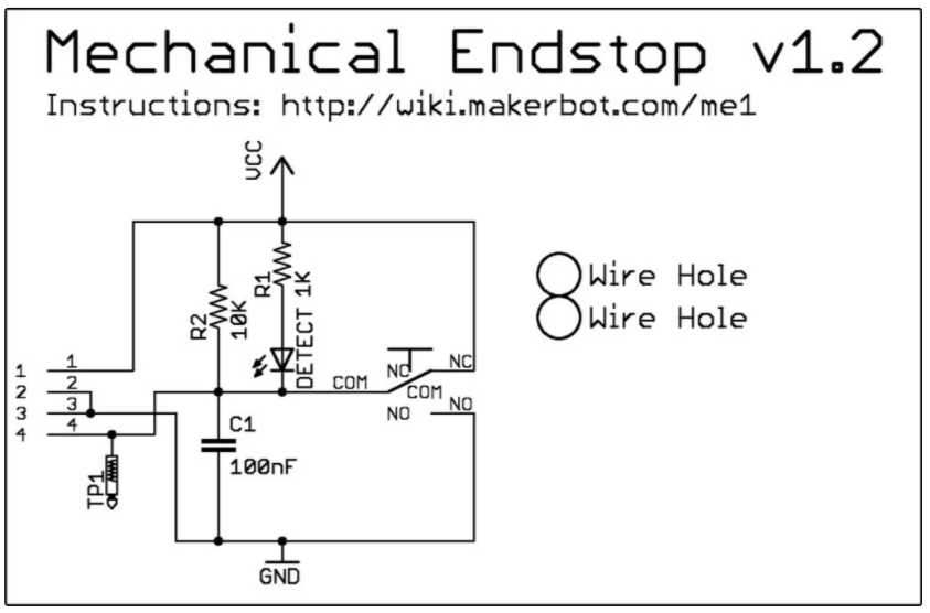
One of the first things to note is the Woodpecker board is designed such the the default switches are expected to be NO (Normally Open, High); The limit is triggered by pulling the signal low (short to ground).  This is unfortunate, as switches will typically fail in the open position. Worse: Perhaps they even become disconnected and stay apparently open during a limit-exceeded condition.

I ordered these switches from ebay. There are similar ones on Amazon. Here's a switch installed in the Y-Axis mount that I designed in Fusion360:


Although there's a wiki link on the board schematic, it has long since disappeared from the internet. Fortunately I was able to recover some key files from the wayback machine, and copied them here for reference (next 5 images credit: Makerbot):


Interface description:


The PCB layout:


Bill of materials:

PCB Render; "The Mechanical Endstop v1.2 is Open Source Hardware and is licensed under the GNU GPLv3":


I needed to measure and create my own mechanical drawing with dimensions:
The PCB supports are 5mm in diameter extrusions, 2.1mm high; The 2 holes are 3.1mm diameter (snug fit). The little nubs on the posts at the end near the connector are an addition 1mm high, 2.9mm diameter. 

I also ordered this Eccentric Work shop CNC optical limit switch isolator. Keep in mind that optical isolation does only that: isolate. This is not a switch debouncer. But then, we'll never need to debounce: the first limit trigger will freeze the controller board. All future signals, limit, G-Code, serial or otherwise will be ignored until the board is reset. 

See the EccentricWorkShop schematic:

At one point, I thought I might need two of these isolator boards, as there is a connection for only 1 wire for each axis. However when looking at the schematic, it appears the limit switch detection is also tied together on the PCB:

And sure enough:


So it appears that when limits are detected, there's no way for the software to determine which limit switch was triggered for a given axis. Although the software would of course know which direction it last send a g-code, so perhaps it could be inferred. Still, if there was a malfunction, it might be nice to know which switch actually triggered.


2* Limit-X-Axis
2* Limit-Y-Axis
2* Limit-Z-Axis
A5 = Probe
A4 =
A3 = Coolant Enable
A2 = Cycle Start/Resume
A1 = Feed Hold
A0 = Reset/About
A7 =
A6 =
D13 = Spindle Direction
RST
5V

And from electrokean:

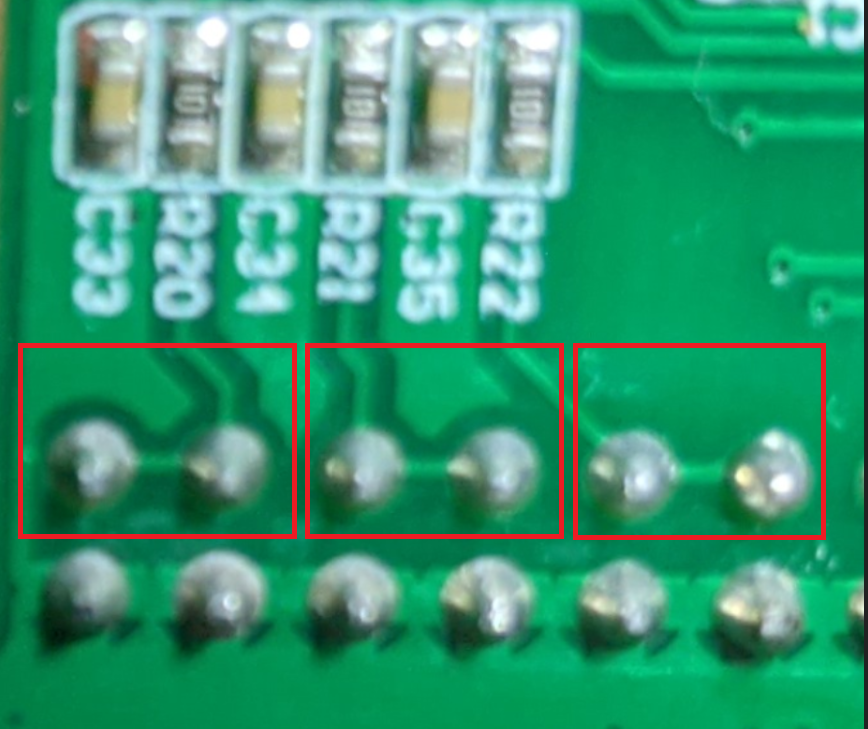
X = D9 = PB1 = pin 13 via R20
Y = D10 = PB2 = pin 14 via R21
Z = D12 = PB4 = pin 16 via R22

My first test drive was rather disappointing. After all that design work for the limit switch mounts, when using the stand-alone controller, nothing happened when running the sample G-Code and the limit switches were manually pressed. I would have hoped the woodpecker board would be interrupt-driven to detect the switch closures regardless of how the g-code arrived. There's a GitHub discussion where rseijo claimed "Zen, Yen & Xen had no connection points to the Atmega328" (confirmed to not be the case for me) and posted this useful header diagram:


As it turns out, the switches are not enabled by default! Thanks Anyzy for this useful tidbit:


Reading the fine print in the text block, we see that hard limits are enabled with $21=1 (of course they are). My $21 was found to be set to zero. Manually setting this to a value of 1 and tada! Upon pressing the limit switch while even manually moving the axis with the external controller, and the motion immediately stopped! See also the grbl documentation wiki.

Of course, there's probably a reason for having the feature disabled by default. Once triggered, all bets are off and the machine can only continue by pressing reset. Any work in progress is lost. Thus if any sort of stray noise or interference triggers the signal, well - that would certainly fall into the "undesired features" category; for example:
The machine stop working randomly with the spindle still running
And sure enough, if you see the settings posted, the $21 is already set on! So stray noise triggering these limit switches is definitely undesired.

I sure wish I had first found the Hackaday article that referred to an informative blog by Shahada Abubakar. One of the things I learned there: the reset switch is only one option to restart after a limit switch has been triggered. The other option:
 "This can be done by sending Control-X followed by $X"
There are additional tips on GRBL setting there, too.


Resources, Inspiration, Credits, and Other Links:


The road to CNC3018 Limit Switches

Almost two years to the day! It was way back in 2018 that I bought my first (and still only) CNC machine to learn more about G-Code and CNC in general. I bought one of the Twowin Tool CNC 3018 Pro machines from on AliExpress. The kit arrived in good shape, having been well packed. Assembly was quite fun and fairly straightforward. In the end I was frustrated that there was no good mounting solution for the limit switches. 


The folks over at LinkSprite have a pretty informative Wiki for desktop CNC.

One of my first CNC projects was this op-amp circuit etched into a bar of soap. (turns out soap is pretty forgiving, and a great way to learn to use a CNC machine). After a couple of sample runs, and my limited free time, it ended up mostly sitting idle in a box. So many cool projects, so little time.


It was about a year later during the summer of 2019 that I ordered the original Prusa i3 mk3s kit. This, too was quite a fun assembly project - although considerably more challenging than the CNC machine. I spent pretty much an entire weekend putting this together. It was really quite rewarding. The assembly instructions are very clear. The process is however quite time consuming. Plus, now I have a new appreciation for gummy bears. 

After assembly and a download or two from ThingVerse, my interest (and free time) waned somewhat. I had poked around a bit with various CAD programs, but nothing really sparked my interest. in printing designs from someone else. The printer then sat idle, too.

So here we are in 2020. I have SO MUCH more free time. Although I put in more hours for the Day Job from home, we don't travel or do much else these days. This leaves plenty of time to explore all these things I've wanted to learn!

It was a couple of months ago that I bought my next item on my list of "always wanted to have, but not sure what I will actually do with it": A reflow oven! I had a lot of fun retrofitting this as described in my prior blog. (it's no fun just to buy something, right?) 


Oddly, this was also the project to bring everything together. I thought it would be cool to etch my own Mylar solder stencil to try out my first SMD PCB: a reason to use the CNC machine! Oh, but the CNC machine needs those limit switches. I can print my own limit switch hardware! Oh, but I had pretty limited experience with mechanical CAD design. I need to learn Fusion360. Good thing that I have plenty of free time at home; chasing another bunny...

Printed books are great for reference, but not the best way to learn something hands-on like CAD software. Yes, there are a lot of YouTube videos, but most seem to be people showing off what can be done, instead of actually teaching the complete newbie, like me. Solution? This Designing for 3D Printing with Fusion 360 on Udemy This is absolutely an awesome class that got me kickstarted in Fusion 360. If you have little or no skills with Fusion 360, I highly recommend this class. Vladimir Mariano is clear, concise, articulate, and a real joy to learn from in this class.

Being able to design parts and print them at home turns out to be quite addicting, particularly if you happen to be a borderline perfectionist. There's somewhat of a chronology in my learning and skills here:


There's apparently a Grbl plug-in for OctoPrint; I'll need to take that for a test drive.

Enough of the background... on to the mounting hardware design...


Resources, Inspiration, Credits, and Other Links:

Sunday, September 27, 2020

Notes on CNC for PCB Milling and SMD Solder Masks

Some time ago I bought a personal CNC machine, as I had always wanted to learn more about gcode and in general what could be done with a home CNC machine. I also used the excuse that I would be able to make prototype PCB quickly. Nearly 2 years later, I have not yet etched a single PCB with it. So many fun projects, so little time! 

The CNC arrived in kit form and required (relatively straightforward) assembly, which was really enjoyable. I ordered this TwoWin Pro 3018 from Aliexpress. It's definitely a low-end CNC machine, but for the price I am quite happy with it. While it is certainly not going to be machining a new engine block - it is completely capable of light-duty PCB etching and similar work.

As noted in my prior blog, I purchased (and "upgraded") a T962A Reflow Oven. There too - the upgrade rework was a lot of fun! In looking at practice SMD boards - I realized that none of them had any sort of stencil. How to make one? Well, I'm thinking of something in Adobe Illustrator that will output a DXF file and convert that to g-code, perhaps with dxf2gcode. (it is a shame the sourceforge site continues to be so riddled with ad-spam but pi-hole really helps block much of the crap), See also grauonline blog: "CNC Milling: From DXF Files to g-code using free software. Note the google drive download link there is a bit dated. 

I ordered some 3 mil Blank Stencil Mylar Sheets that should be here next weekend. From what I could tell from a variety of google searches, the thinner 3 mil mylar should have less of a tendency to have the solder paste stick when removed from the PCB. We'll see.

There's definitely a learning curve for any CNC machine. I somewhat lost interest out of frustration in converting file formats from various editors to g-code. I spent a bit of time learning Fusion 360. It is great for drawing, but getting the data out to actually machine something is another story. Note that Fusion 360 is a cloud product, and the files are stored primarily in the cloud.

Here's a guy that says "It is possible to do PCBs on this sort of set up but it is not easy to get good results."

View Gerber files online for free at gerblook.org.

More recently, I found this pcb2gcode that will taker gerber files directly from KiCAD and generate g-code (the commandline parameters are somewhat extensive, so the pcb2gcodeGUI is recommended).

Install of pcb2gcode and pcb2gcodeGUI was fairly straighforward on WSL:
cd /mnt/c/workspace
sudo apt-get update
sudo apt-get install git build-essential automake autoconf autoconf-archive 
sudo apt-get install libtool librsvg2-dev
sudo apt-get install libboost-program-options-dev libgtkmm-2.4-dev gerbv 
git clone https://github.com/pcb2gcode/pcb2gcode.git
cd pcb2gcode

autoreconf -fvi
./configure
make
sudo make install

cd /mnt/c/workspace
sudo apt-get install build-essential git qt5-default libqt5svg5-dev
git clone https://github.com/pcb2gcode/pcb2gcodeGUI.git
cd pcb2gcodeGUI/
qmake
make
sudo make install
Of course to actually run on WSL, an X-Windows server is needed, such as VcXsrv. It can be either run from C:\Program Files\VcXsrv\ or launched directly from WSL:

"/mnt/c/Program Files/VcXsrv/vcxsrv.exe" & pcb2gcodeGUI & 
    
Note that both the Windows vcxsrv.exe and the pcb2gcodeGUI are blocking apps. So instead of having 2 additional, blocked WSL windows, the ampersands allow the commands to be launched in parallel. The trailing " & " allows for return to current terminal bash prompt (just press enter).
There are some comments about disabling OpenGL. I did have an odd problem with sigrok pulseview not sizing properly. Note to self to revisit the thread on discord to see if the OpenGL settings have any effect (in particular the iua for iCEBreaker).

There's the option of export LIBGL_ALWAYS_INDIRECT=0 or the passing the -wgl to vcxsrv. Note also the export LIBGL_ALWAYS_SOFTWARE=1 mentioned in the comments of my RISC-V on tinyFPGA-BX via WSL blog.

Note that most of the inexpensive CNC machines doe not have limit switches pre-installed. I bought some of the markerbot-style boards

There's a comment on GitHub about "endstop PCBs connect the NC switch terminal directly to +5 V, in addition to having a pullup resistor on the C terminal" so care should be taken on the wiring. This is easily solved by snipping off the NC pin as show on the MPCNC: Makerbot-style Endstop Switch Modification blog.

Saturday, August 22, 2020

Notes on Upgrading T962A Reflow Oven

I bought my first-ever reflow oven! 

I've been wanting to learn to solder SMD devices in a reflow oven for a long time. I've had my eyes on that toaster oven conversion for quite a while - to the point of having the target oven in my "save for later" cart at Amazon. In the end, I chose to buy a real oven.

There are tons of them for sale from a variety of vendors with probably an equal variety of reputations. I bought this one from the sm18595638214-4 seller on ebay for no particular reason other than 97%+ reputation and over 60 units sold. Despite the profile saying "Based in China", reading the small print it actually ships from USA. My oven was shipped from Southern California and arrived in only a few days via FedEx (shipping included in price!) The manufacturer is Tai'an Puhui Electric Technology Co., Ltd (see also their T-962 product page with quite a few PCBA machines for sale). 


What's the first thing to do? Open it up and modify it, of course! I mean, seriously: how could this invitation be refused:


I received the Jilles stamp of approval:


All joking aside:

DANGER: there is high voltage, potentially lethal inside! Do not attempt modifications unless you have proper training. Ensure the power is always completely removed from the oven (not just turned off) when touching anything inside. 

There are actually a variety of different methods for upgrading a T-962. These are my notes as I follow along the 1bitsquared Upgrading a T962a Reflow Oven blog. My notes here are somewhat of a supplement and note-to-future-self as his documentation is quite good. Still, I had my own questions and challenges.

I'd like to extend a special thanks to @esden for giving me a heads up when he had one of his Improved Thermocouple Interface boards for sale. He's a really great guy that I had the pleasure of  meeting at the Hackaday Supercon. I highly recommend supporting him by shopping at 1bitsquared. Be sure to check out his twitch stream and discord (invite).

Thanks also to Unified Eningeering for the open source design on the Better Thermocouple Interface.

Here's a picture of my board made by Piotr: 


It is tiny! Actually, I think it should really be a bit bigger. There's plenty of space in the oven, and I had a difficult time inserting the thermocouples (with relatively large connectors) into the green header. Note there are 4 channels available for thermocouples. The oven comes equipped with only two.

Essentials:
Optional Items:

Things to review in advance:

My unit had some sharp edges on the drawer. Some fine sandpaper is wise to round them a bit so fingers are not cut.

I powered up the unit to make sure it was at least operational. The first thing I noticed is that the little  fan is indeed rather loud. Unless the oven is used a lot, I later learned that this fan is only used to attempt to keep the cold junction as a reasonable temperature- so it could probably be removed altogether. Probably just as well to replace it.

I had a difficult time removing the drawer. The instructions where to "lift the black latch". On my unit, the one on the left is released by pushing up. However the latch on the right is released by pushing down. I of course started on the right. Perhaps no big deal - but keep in mind the rails are also sticky with lubricant.

Push the black lever up on the left:


Push the black lever down on the right:


The first modification is probably the most important. Although my unit did have continuity from case to ground plug connection, there was pretty limited contact surface with the anodized case:


Although my unit was apparently assembled just last year, in September of 2019, the was a ton of the masking tape, just as described in other blogs. I had hoped the manufacturer would have changed this as there are so many comments on the bad smell of the heated masking tape once the oven is in use. 


Be careful pulling it off to ensure the aluminium foil does not tear:


One roll of kapton tape was more than enough to replace the masking tape to insulate the electronics from the aluminum foil. I use a bit extra as additional strain relief on the thermocouple wires:


Regarding the fan install, I suggest doing this first. Mine was so obnoxiously load I ended up cutting the wires just to silent it. (There's no fan check circuitry) Oh, and this specific fan needs to have the hole drilled out with a 1/8" bit. Perhaps the existing screws could be force-tapped into the plastic, but I didn't want to break it.

Piotr mentions disconnecting the solid state relay connection, but does say why. Putting my board into bootloader mode immediately shows why this is a good idea: mine turned on! I'm glad the SSR was disconnected. It was a bit startling, as I had never heard the large fan running. Other than the power-up test, I proceeded directly to modification.

Perhaps you've noticed this in the better thermocouple interface page


That's the cold-junction sensor down in the lower right. But notice the yellow circle. It sure looks like the Vdd and GND pins are tied together to ground. Sure enough, this is consistent with the schematic in that both DS18B20 pins are grounded. This is a clever idea, as from the datasheet (see page 7), this device has a parasite mode:


Still, it may not be clear as to why this cold junction sensor is on the main board, at the old junction, and not on the new mod board. It is a leftover from a prior upgrade, as there's a note "the cold-junction sensor is still present on my board, but not used when the external TC IF is detected".


Ok, so on to the upgrade!

Key to the firmware upgrade is the ISP connector:


Although a variety of hardware programmers are possible, I used a simple USB to TTL device and manually fiddled with the ISP and Reset lines. 

Fortunately the manufacturer kindly installed a header. Here's a picture of it on the board:


As usual, the connections are "crossover": Connect Tx (Transmit) of the USB device to the Rx (Receive) on the board, and Rx to Tx.

WARNING: Is is never a good idea to attempt to communicate or flash a device that is not already powered up.

From the factory, the new firmware is programmed with FlashMagic by: 
  • Connect ISP to ground
  • Momentarily connect RESET to ground
  • Release ISP from ground
The the new firmware, the unit should be able to go into bootloader mode by holding down the F1 when turning on the oven.


After the new firmware is in place, run it by again bringing the RESET line momentarily low (to ground).  To see the bootup messages, run Putty at 115200 8N1. The FlashMagic software may need to be shutdown if it still has the USB device in use.

Here's my setup:


Not shown: I used another USB device (the SPIDriver) that has a couple of header pins exposed for ground connections.

My first attempt was to see if the FlashMagic could see my device. I was initially concerned that my software only showed half the number of communication parameters. Perhaps they only show up if you have a hardware programmer plugged in? In any case, I had no opportunity to select an interface or oscillator frequency as shown in the Flashing the LPC21xx controller section of the UnifiedEngineering T-962-improvements wiki. Note the device selected is the LPC2134:


Next, "just in case" something went wrong (or you never know, you might need that someday), I saved the original firmware. Twice. Click on ISP - Read, and then click on the Export Memory tab:


The next step could be a point of no return. Hey, we're here to void warranties, right?

For my first attempt, I used known good file (version 0.5.2) from the assets on the releases page, last built in 2018.

If instead you want to build the firmware from scratch (here shown for WSL):
// over a gig of disk space is needed iss you don't have gcc-arm-none-eabi already installed
sudo apt-get update
sudo apt-get upgrade
sudo apt-get install binutils-arm-none-eabi
sudo apt-get install gcc-arm-none-eabi 

cd /mnt/c/workspace/
cd T-962-improvements
make
// see file: ./build/T-962-controller.hex 
The compiled current code in GitHub did *not* match the releases file for me.

Somewhat surprisingly, the upload of firmware went really quite smoothly, despite my software missing half of the available parameters:


When the FlashMagic app is sized relatively small - note the "Start" button to begin upload is in the lower right may not be immediately obvious.

I had initially upgraded the firmware before installing the 1bitsquared Improved Thermocouple Interface upgrade module. As everything seems to work well, I proceeded with that modification.

The 3 connections of interest are power, ground, and data:


Another seeming invitation to modification was the convenient 3 square pads, shown with my wires already connected:


Connection of the board was pretty straightforward. Here's the an initial working modification:


Edit: I didn't really like the tape method shown above for the new thermocouple interface, as the tape does not stick as well to the cabinet as one might like. So I added these tie wraps:


Note the main strain relief (1) for the fairly rigid thermocouple wires. There's another tie-wrap (2) in the empty PCB hole - positioned to keep the next tie wrap (3) on the thermocouple wires away from the main PCB. This tie wrap has the respective tail taped down as an extra measure of stability. In addition to the kapton tape underneath, there's a small piece of card stock under the tape (part of the fan packaging was used here) for additional electrical insulation. By far the (1) tie-wrap does most of the work to keep the new interface board in a stable position. 

A better solution would be to drill a couple of mounting holes instead of the (2) and (3) tie wraps. I will probably do that when my other 2 K-Type thermocouples arrive. Alternatively, cable management clips might work (depending the strength of the adhesive)

Back to the project blog from that initially working state...

However this is where things took a turn for the worse. I powered on the unit. The display was blank! Oh no! How could that be? I took a short break to think about it. Was this the end? $400 down the toilet?

I refused to give up. I'm not new at this. Prior to being only a software engineer, I spent nearly a decade at a small industrial manufacturing company, building and repairing all sorts of crazy things big and small. I didn't do anything wrong here. No magic smoke, no mishaps. What went wrong?

So ok, let's backtrack. What's different? Well the Thermocouple board is connected, but duh, how could that affect this display. It shouldn't... but let's go back to a known working state. I removed the board. Nothing. Still a blank display at power up. No fun if it is too easy, right? Could it have damaged the display? No way.

Perhaps the firmware got corrupted and crashed? I hooked up the computer again, flashed fresh firmware. Success! Ok, cool, that was odd, but let's proceed. 

I reconnected thee thermocouple board. The display was blank again! Are you kidding me? So let's repeat the routine: remove thermocouple board, fresh firmware, it works! Ok, fool me once...

Clearly something else going on here. So instead of flashing firmware, I hooked up that serial port to see what sort of messages are displayed at startup time. It's completely happy! No indication of problem, erm - other than the blank display.


How can that be? Well, since I had everything hooked up again, it was easier to restart by bringing the RESET pin low, instead of reaching for the power switch. Success! Yes, after a reset - the display works just fine. This was never about the external board or the firmware. It was always about the after-powerup reset.That certainly falls into the undesired feature category.

How can this be a problem? The factory firmware certainly did not have this issue. The Microcontoller does indeed have reset startup circuity built in. Is this is a software issue or a hardware issue?

There's a mystery mod that I have not been able to identify:


I remember seeing these resistors when reading about the mod before ordering my oven. Note not only the radial-lead resistors tacked on o the chip, but there's also a small SMD (probably a pullup) on the thermocouple board connection. I wonder what they do? Surely resistors alone will not resolve the new-found reset problem.

I'm not the first person to encounter this issue, however @tnt completed this process in January with no problems (but he also built from the git repo).

Ok, so I needed find a solution for the reset problem. Perhaps some sort of RC delay? That seems too hackish. It may be temperature related, as upon fresh power up later in the day, I didn't the reset problem at all. The display is working fine. Even waiting only a couple of second after power down and turning on the oven - the display is working fine. Then few hours later, the display problem had returned! This time it may have been in bootloader mode as the big fan came on while the display was blank and the heater came on!! I thought that the problem may be related to my franken-ribbon cable on the ISP (see below) - but no, removing that completely and random startup problem remained.

Reminder: The display is supposed to be blank in bootloader mode. But the unit should never boot into bootloader mode when simply powering up.

Ok, so if we take another look at the reset circuitry (above)... well, there is none. ~RESET on pin 57 appears to just go straight to the header. 

Two of the most common solutions to the worlds problems are (1) decoupling capacitors and (2) pullup resistors. Pullup it is! As it turned out, there's a large through-hole nearby that has 3v3 available:


I crimped a 10K resistor to the header connector on the reset line. Here is is with the heat-shrink insulation not yet in place:


Voila! So far, so good! I've not yet seen the blank display problem return!

As the header access is buried inside, I wanted something a bit more accessible. I started this portion of the project early on - long before I know about the reset problem. 

I spent a relatively large percentage of the upgrade time manually assembling the header cable and assembly:


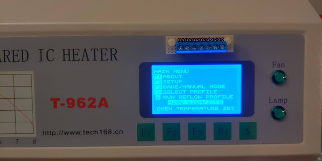
If there was ever something to void my warranty, I'm pretty sure the holes drilled in the front panel did it:


In the end I have a reflow oven that is immediately recognized as mine:


A little "Frankenstien-ish", no?

That front-panel mounted PCB was probably not my ideal choice. I had considered something on the back of the unit where it belongs, but really, all of the electronics are at the front. A rear mount would need long cables routed. My ideal solution would have been a recessed header, perhaps even with some sort of protective trap door cover. Alas I don't have anything to poke a square hole into the case. I used what I had on hand. 

Note the manufacturer-supplied manual included this text:

Attention: This machine can't be used to solder components (like chips with metal encapsulation of strong reflective material) and the "plastic plug in board" which can't be heated up to temperatures of 250 degrees centigrade"


Sunday, August 9, 2020

Sigrok on WSL for iua: ice40 USB Analyzer

In my previous post on the iCEBreaker Bitsy FPGA - early adopter version, I mentioned the interesting iua: ice40 USB Analyzer project that I learned about on the iCEBreaker discord channel in the context of troubleshooting the odd problem I was seeing on my "Power Share" USB3.0 port.

There's minimal documentation on Getting Started, so here I am creating my notes.

The iua is meant for the iCEBreaker, not the Bitsy (although I wonder if it would still work on the Bisty? another rabbit hole for another day...)

As with all prior posts, I'm a Visual Studio developer at the day job, and continue that with my FPGA learning on the weekends... thus I use Windows, WSL, and Visual Studio here.


cd /mnt/c/workspace/
git clone https://github.com/smunaut/iua.git
cd iua/hdl
make

As reminder, if you have a VM running, make sure you are not having problems with a prompt awaiting device connection:

Also, even if you've used iceprog before and it decides to not find the icEBreaker today, check the drivers with Zadig. Windows seems to like to replace the drivers during updates. The iCEBreaker needs the libusbK drivers.

Unlike the Bitsy that needs to have bootloader boot set by holding the button at power-on time for dfu-util, the iCEBreaker does NOT need that when using iceprog

As there's no native USB support in my WSL, I use the DOS exe to send the binary to the device either from DOS:

C:\workspace\ulx3s-toolchain\bin\iceprog.exe 

or from WSL:

/mnt/c/workspace/ulx3s-toolchain/bin/iceprog.exe iua_icebreaker_top.bin
When successful, there should be output that looks something like this:

init..
cdone: high
reset..
cdone: low
flash ID: 0xEF 0x40 0x18 0x00 0x00 0x00 0x00 0x00 0x00 0x00 0x00 0x00 0x00 0x00 0x00 0x00 0x00 0x00 0x00 0x00
file size: 104090
erase 64kB sector at 0x000000..
erase 64kB sector at 0x010000..
programming..
reading..
VERIFY OK
cdone: high
Bye.


So that was the easy part. (The easy part is always the thing you already know). The next part - sigrok - is something that I've wanted to learn more about for quite some time. There's another smunaut/libsigrok project needed, which is a modified fork of sigrokproject/libsigrok and needs to be built like this:

git clone git://sigrok.org/libsigrok
cd libsigrok
./autogen.sh
./configure
make


People often ask why I deal with the annoyances of Windows. Well, Linux has plenty as well, imho. I had most of the dependencies already installed, but receieved this error diring make
configure: error: Package requirements (glib-2.0 >= 2.32.0 libftdi1 >= 1.0 libusb-1.0 >= 1.0.16 gio-2.0 >= 2.24.0 libzip >= 0.10) were not met:

No package 'libzip' found


And so what's the first thing to try? Well, sudo apt-get install libzip, right? Nope. :/

Reading package lists... Done
Building dependency tree
Reading state information... Done
E: Unable to locate package libzip


grumble, grumble, google, grumble....

There's only one reference on the wiki, and it only notes I need libzip >= 0.10. But where to find it? Ah yes, it is just the development code library, not a tool, so we need the -dev suffix:

sudo apt-get install libzip-dev


Ok, now to run ./configure again...

Closer this time; I am still missing some things:

Enabled language bindings:
 - C++............................. no (missing: glibmm, Doxygen)
 - Python.......................... no (missing: C++ bindings, PyGObject, SWIG)
 - Ruby............................ no (missing: C++ bindings, SWIG)
 - Java............................ no (missing: C++ bindings, SWIG, JavaC, JNI headers)

===============================================================================
WARNING WARNING WARNING WARNING WARNING WARNING WARNING WARNING WARNING WARNING
===============================================================================
===                                                                         ===
===         The libsigrok C++ bindings are not being built since you        ===
===             are missing one or more dependencies (see above)!           ===
===                                                                         ===
===      This means you won't be able to compile frontends that require     ===
===  the C++ bindings (such as PulseView)! You also won't be able to build  ===
===     other bindings and frontends using those (such as sigrok-meter)!    ===
===                                                                         ===
===============================================================================
WARNING WARNING WARNING WARNING WARNING WARNING WARNING WARNING WARNING WARNING
===============================================================================


ugh.
gojimmypi:/mnt/c/workspace/libsigrok
$ sudo apt-get install glibmm
Reading package lists... Done
Building dependency tree
Reading state information... Done
E: Unable to locate package glibmm
gojimmypi:/mnt/c/workspace/libsigrok
$ sudo apt-get install glibmm-dev
Reading package lists... Done
Building dependency tree
Reading state information... Done
E: Unable to locate package glibmm-dev
gojimmypi:/mnt/c/workspace/libsigrok


grumble, grumble, google, grumble....

This one requires a version number in the name. Of course it does. So onward to install: glibmm. I'll grab doxygen too, and then one more ./configure as well:

sudo apt-get install libglibmm-2.4-dev
sudo apt-get install doxygen
./configure


No warnings! Hurray!! So on to a (very long running) make, then:

  
$ make check
make
make  all-am
make  check-TESTS
============================================================================
Testsuite summary for libsigrok 0.6.0
============================================================================
# TOTAL: 0
# PASS:  0
# SKIP:  0
# XFAIL: 0
# FAIL:  0
# XPASS: 0
# ERROR: 0
============================================================================


$ sudo make install
 /bin/mkdir -p '/usr/local/lib'
 /bin/bash ./libtool --silent  --mode=install /usr/bin/install -c   libsigrok.la bindings/cxx/libsigrokcxx.la '/usr/local/lib'
libtool: warning: relinking 'bindings/cxx/libsigrokcxx.la'
 /bin/mkdir -p '/usr/local/include/libsigrokcxx'
 /usr/bin/install -c -m 644 bindings/cxx/include/libsigrokcxx/libsigrokcxx.hpp '/usr/local/include/libsigrokcxx'
 /bin/mkdir -p '/usr/local/include/libsigrok'
 /usr/bin/install -c -m 644 include/libsigrok/libsigrok.h include/libsigrok/proto.h '/usr/local/include/libsigrok'
 /bin/mkdir -p '/usr/local/share/mime/packages'
 /usr/bin/install -c -m 644 contrib/vnd.sigrok.session.xml '/usr/local/share/mime/packages'
 /bin/mkdir -p '/usr/local/share/icons/hicolor/48x48/mimetypes'
 /usr/bin/install -c -m 644 contrib/libsigrok.png '/usr/local/share/icons/hicolor/48x48/mimetypes'
 /bin/mkdir -p '/usr/local/share/icons/hicolor/scalable/mimetypes'
 /usr/bin/install -c -m 644 contrib/libsigrok.svg '/usr/local/share/icons/hicolor/scalable/mimetypes'
 /bin/mkdir -p '/usr/local/include/libsigrokcxx'
 /usr/bin/install -c -m 644 bindings/cxx/include/libsigrokcxx/enums.hpp '/usr/local/include/libsigrokcxx'
 /bin/mkdir -p '/usr/local/include/libsigrok'
 /usr/bin/install -c -m 644 include/libsigrok/version.h '/usr/local/include/libsigrok'
 /bin/mkdir -p '/usr/local/lib/pkgconfig'
 /usr/bin/install -c -m 644 libsigrok.pc bindings/cxx/libsigrokcxx.pc '/usr/local/lib/pkgconfig'  


Next is to install decoder:
git clone https://github.com/sigrokproject/libsigrokdecode.git
cd libsigrokdecode
./autogen.sh
./configure
make
sudo make install


Next is to install Pulseview! (see also build info). Despite having the requirements installed, I also needed:

sudo apt-get install qttools5-dev


git clone https://github.com/sigrokproject/pulseview.git
cd pulseview
cmake .
make
sudo make install


Still following along? After all this, it is time to actually run pulseview! Alas on WSL we have an extra challenge: X-Windows. I'm using vcxsrv from the ad-spam-ridden sourceforge. (it is really a shame to see what that site has become).

C:\Program Files\VcXsrv\vcxsrv.exe


See building libsigrok, but use the smunaut/libsigrok

sudo apt-get install git-core gcc make autoconf automake libtool
git clone https://github.com/sigrokproject/libserialport.git  
cd libserialport
./autogen.sh
./configure
make
sudo make install 


git clone https://github.com/smunaut/libsigrok.git smunaut-libsigrok
cd smunaut-libsigrok
./autogen.sh  
./configure
make
sudo make install


See build failure for smunaut/libsigrok #2

If after doing a make clean for pulseview, and an error like this is enountered:
$ make
[  1%] Automatic MOC for target pulseview
[  1%] Built target pulseview_autogen
make[2]: *** No rule to make target 'l10n/de.qm', needed by 'qrc_translations.cpp'.  Stop.
CMakeFiles/Makefile2:67: recipe for target 'CMakeFiles/pulseview.dir/all' failed
make[1]: *** [CMakeFiles/pulseview.dir/all] Error 2
Makefile:151: recipe for target 'all' failed
make: *** [all] Error 2


The problem seems to be that make clean improperly deletes a couple of files:

gojimmypi:/mnt/c/workspace/pulseview
$ git status
On branch master
Your branch is up to date with 'origin/master'.

Changes not staged for commit:
  (use "git add/rm <file>..." to update what will be committed)
  (use "git checkout -- <file>..." to discard changes in working directory)

        deleted:    l10n/de.ts
        deleted:    l10n/es_MX.ts

no changes added to commit (use "git add" and/or "git commit -a")
gojimmypi:/mnt/c/workspace/pulseview


So simply put them back:

git checkout master
git checkout l10n/de.ts
git checkout l10n/es_MX.ts  


Despite
gojimmypi:/mnt/c/workspace/smunaut-libsigrok
$ ./configure
...
Detected libraries (optional):
 - libserialport >= 0.1.1.......... 0.1.1


I still saw wthis error:
pulseview: error while loading shared libraries: libserialport.so.0: cannot open shared object file: No such file or directory  


sudo apt-get install libserialport-dev 


Saturday, August 8, 2020

iCEBreaker Bitsy FPGA - early adopter version

A couple of weeks ago, I ordered the early adopter iCEBreaker bitsy FPGA board. It arrived promptly just a few days later!


Key details:
  • Use dfu-util to upload binary files to the Bitsy (see Windows binaries)
  • The board needs to be in DFU boot mode to upload FPGA bin file
  • Hold button down when powering on device to enter DFU boot mode
  • Click button while in DFU boot mode to exit boot mode
  • FPGA Toolchain needs to be installed.

Note that I am using WSL on Windows. All the FPGA synthesis stuff happens in WSL. However, there is no native USB support in my WSL 1, so I use the DOS executables (either from WSL or Windows DOS prompt) for the actual device programming. Although I have several blog entries that mention this topic, I have a summary for Programming FPGA Devices from WSL.

For open source toolchain, you can install everything from GitHub, or use Multi-platform nightly builds of open source FPGA tools. I also have a Visual Studio FPGA Extension that will soon build and upload from the comfort of the VS IDE. (currently, the release only does syntax highlighting)

Unlike the similarly named iCEBreaker, this board does NOT use iceprog to upload binaries.
 
If when running dfu-util.exe -l, the device cannot be seen:

dfu-util 0.9

Copyright 2005-2009 Weston Schmidt, Harald Welte and OpenMoko Inc.
Copyright 2010-2016 Tormod Volden and Stefan Schmidt
This program is Free Software and has ABSOLUTELY NO WARRANTY
Please report bugs to http://sourceforge.net/p/dfu-util/tickets/


Make sure you are using a known good USB cable. Recall the button needs to be pressed before power is applied. There's apparently an issue with USB3.0 PowerShare ports. Try using a different port, or perhaps a USB hub.

 
If when running dfu-util.exe -l, the device cannot be opened:

Cannot open DFU device 1d50:6146

C:\Users\gojimmypi>C:\Download\dfu-util\dfu-util.exe -l
dfu-util 0.9

Copyright 2005-2009 Weston Schmidt, Harald Welte and OpenMoko Inc.
Copyright 2010-2016 Tormod Volden and Stefan Schmidt
This program is Free Software and has ABSOLUTELY NO WARRANTY
Please report bugs to http://sourceforge.net/p/dfu-util/tickets/

Cannot open DFU device 1d50:6146


This typically means the Windows drivers are not installed. Zadig to the rescue:


If when running dfu-util.exe -l, the device is working properly:

dfu-util 0.9

Copyright 2005-2009 Weston Schmidt, Harald Welte and OpenMoko Inc.
Copyright 2010-2016 Tormod Volden and Stefan Schmidt
This program is Free Software and has ABSOLUTELY NO WARRANTY
Please report bugs to http://sourceforge.net/p/dfu-util/tickets/

Found DFU: [1d50:6146] ver=0004, devnum=12, cfg=1, intf=0, path="1-1.3", alt=1, name="RISC-V firmware", serial="your serial"
Found DFU: [1d50:6146] ver=0004, devnum=12, cfg=1, intf=0, path="1-1.3", alt=0, name="iCE40 bitstream", serial="your serial"

We can proceed to actually programming the FPGA.

From what I can tell, it seems the Bitsy is iCEBreaker compatible:
cd /mnt/c/workspace
git clone https://github.com/icebreaker-fpga/icebreaker-examples.git
cd icebreaker-examples/blink_count_shift
make

To program the Bitsy, as there are multiple, identical DFU numbers, the "alt" needs to be specified:

dfu-util.exe -a 0 -D blink_count_shift.bin

Beyond blinky, a pinout is useful: 

iCEBreaker Bitsy Pinout by 0xdec

There's a main repo: https://github.com/icebreaker-fpga/icebreaker-examples but I learned on the discord channel that the code for the Bitsy has not yet been pushed there.

That repo will likely at some point have all the latest code. For now it is still in esden/icebreaker-examples
git clone https://github.com/esden/icebreaker-examples.git esden-icebreaker-examples  
cd esden-icebreaker-examples
git branch --all
git checkout bitsy
cd blink_count_shift  
make clean
make BOARD=bitsy1  
Note the `make` will be expecting parameters:

$ make
../board.mk:18: *** Please specify BOARD, options are "icebreaker", "bitsy0" or "bitsy1".  Stop.


then upload:
dfu-util.exe -a 0 -D C:\workspace\esden-icebreaker-examples\blink_count_shift\blink_count_shift.bin

Here we should be able to press the Bitsy button to get the green LED to illuminate.

Beyond blinky, I learned there's a DFU UART on FPGA pin 44 (aka IOB_4a, aka P2).

Hookup a USB Serial Port and at DFU boot time at 1000000 baud, a message is displayed:
  
Booting DFU image..
Flash Manufacturer : ef 40 18
Flash Unique ID    : e4 69 98 d2 43 59 15 2f
Command>  

I also learned on discord that USB signals-D/+D are actually 3.3V, even though the supply voltage is 5V

There's this interesting iua: ice40 USB Analyzer that is meant to run on an iCEBreaker FPGA that can apparently be used to "dump all the USB traffic". Note there's an minor problem building, but I have a PR to fix that. (thanks to @tnt on discord for the info). Basically just needed to add a magic parameter --placer sa to run nextpnr like this:

nextpnr-ice40 --placer sa  --up5k --package sg48 --json iua_icebreaker_top.json --pcf ../impl/iua_icebreaker_pins.pcf --asc iua_icebreaker_top.asc --freq 50  

This will happen during make.

Also from @tnt on discord:
There are debug pads on the bity bottom where you can easily solder a header.
set_io -nowarn usb_dp_pad 31
set_io -nowarn usb_dn_pad 34

 Those are the fpga pins where to connect on the icebreaker side.


To be continued in my next post... Sigrok on WSL for iua: ice40 USB Analyzer


Find gojimmypi at gojimmypi.github.io

I'm currently working on my new blog home at  gojimmypi.github.io After implementing a variety of features such as dark mode , syntax hi...