Sunday, March 29, 2020

LiteX Soft CPU on the ULX3S - reloading firmware without reflashing the soft CPU

My next post (aka notes to self) on getting a RISC-V compiled app onto the ULX3S using LiteX.

TL;DR; press the reset button!

Quite a diversion from my day job with SQL and C# and web apps is this fascinating world of soft CPU's and embedded devices. Here's what I learned this weekend:

In my prior blogs, I considered getting Circuit Python running on the ULX3S. There are a lot of moving parts, so I got started with implementing the RISC-V soft CPU on the FPGA. Recall we cannot run Circuit Python on the ESP32 because of hardware limitations (missing USB OTG), however the ESP32-S2 will (in theory) work with Circuit Python. Next, I rambled on a bit regarding various features of LiteX that I was exploring in my prior blog, in the end creating a soft_cpu.sh script with everything I learned.

Refresher:  Onboard the ULX3S is an ECP5 FPGA. We first need to create a soft CPU bitstream that is loaded onto the ECP5. LiteX also creates a BIOS that gets loaded over the serial port. Ok, all fine and dandy, but I seem to only be able to load that BIOS once and then the terminal becomes unresponsive. This makes sense, as the processor stays in the while loop after liftoff. The bios does not appears to be an RTOS.

ULX3S shown with FPGA/BIOS/firmware programming USB cable

Supposedly that BIOS should be able to reload firmware apps. Well, there's this mystery boot_helper. What does this extern do? I suspect that's what loads the BIOS. Then what? There's this 4 line boot-helper-picorv32.S file. Not much help there. The "What is LiteX" introduction does seem to indicate that the development cycle includes reloading the soft CPU, as the "design flow in a nutshell" indicates going back to step 1. I'd like to go back to step 6, skipping the re-synthesis of the soft CPU every time I change the firmware.

The LiteX for the ULX3S has a serial port configured as Tx on Pin L4 (FTDI RxD) and Rx on Pin M1 (FTDI TxD). See the schematic. These pins are not available on either of the external ULX3S headers.

FTDI RxD/TxD USB Serial on ULX3S FPGA pins L4 and M1
I had thought perhaps the BIOS would be looking on a pair of pins implemented in the FPGA as a serial port. Nope. Those pins are definitely hard wired the the FTDI USB serial port.

So what else is there? Well, the BIOS is clearly not an RTOS. So we're definitely waiting forever and doing nothing in that while (1) statement. How else does a CPU begin again? Reset of course! Check out the rst implementation in LiteX. It is hooked to R1 of the FPGA. What's that?

R1 (aka BTN_F1) on the ULX3S
That's the F1 button!! (The "Fire 1" position when the ULX3S is in gamer mode! lol). This is also labeled as "B1" on the PCB, located near the SD card, right under the text "2.5V/3.3V"

It turns out the architecture is not [CPU] - [BIOS] - [firmware]. Instead, the simpler: [CPU (with tiny, baked in BIOS] - [BIOS (with external firmware)].  Now, one could certainly write something in the BIOS to, say load an OS. But that's not what LiteX is doing out of the box in this example.

The architecture naming is a bit misleading, as there is part of the CPU implemented as a BIOS as seen at processor boot time on the LiteX. Unfortunately the external "C" program is also called BIOS (firmware).


So just leave litex_term running and press the F1 (CPU reset) button to reload the BIOS firmware. See my soft_cpu.sh bash script. Each time you update and compile the BIOS code, press the F1 button to reload it onto the soft CPU.

I've created LiteX Pull Request #445 that adds some comments to hopefully help others that may encounter these issues.

How many times can an FPGA be reprogrammed? Well, the folks at Numato claim "SRAM based FPGAs can be programmed as many times as necessary. There is no limit..."

There's also the possibility of using a logic analyzer internally to the FPGA. Also mentioned in the What is LiteX is something called litescope. See the Debugging with ChipScope for more information, as there's not much in the Wiki as of the data of this blog. The architecture image provides some insight. See also the test_analyzer.py.

So now.. I wonder if I can single-step code soft CPU code with OpenOCD. And that litescope! That sounds super interesting...

Saturday, March 28, 2020

RISC-V on the ULX3S with LiteX - Part 2

First .. the exciting news: With 24 days still left in the Crowd Funding Campaign, the ULX3S is within a few dollars of reaching their $40K stretch goal!! I'm so happy to see their success. I've been super happy with mine. (Edit: now nearly 300% funded by the time I publish this!)

TL;DR: Check out this soft_cpu.sh script used to create a soft RISC-V CPU on the ULX3S.

Back to my fomu! I revisited the Adafruit Feather M0 Express - A request for the USB device descriptor failed: Issue #293 on GitHub in the hathach/tinyusb repo. The suggestion was to simply update my fomu to see if the Feather M0 problems would go away:

The last few lines of the release.sh
dfu-suffix -v 1209 -p 70b1 -a $output/${platform}-updater-${release}.dfu
dfu-suffix -v 1209 -p 70b1 -a $output/${platform}-foboot-${release}.dfu
but I saw an error when trying to do that:
C:\Download\dfu-util>dfu-suffix -v 1209 -p 70b1 -a fomu\hacker-updater-v2.0.3.dfu
dfu-suffix (dfu-util) 0.9

Copyright 2011-2012 Stefan Schmidt, 2013-2014 Tormod Volden
This program is Free Software and has ABSOLUTELY NO WARRANTY
Please report bugs to http://sourceforge.net/p/dfu-util/tickets/

Please remove existing DFU suffix before adding a new one.
so I next tried using dfu-util, as noted here:
C:\Download\dfu-util>dfu-util -D fomu\hacker-updater-v2.0.3.dfu
dfu-util 0.9

Copyright 2005-2009 Weston Schmidt, Harald Welte and OpenMoko Inc.
Copyright 2010-2016 Tormod Volden and Stefan Schmidt
This program is Free Software and has ABSOLUTELY NO WARRANTY
Please report bugs to http://sourceforge.net/p/dfu-util/tickets/

Match vendor ID from file: 1209
Match product ID from file: 70b1
Opening DFU capable USB device...
ID 1209:5bf0
Run-time device DFU version 0101
Claiming USB DFU Interface...
Setting Alternate Setting #0 ...
Determining device status: state = dfuIDLE, status = 0
dfuIDLE, continuing
DFU mode device DFU version 0101
Device returned transfer size 1024
Copying data from PC to DFU device
Download        [=========================] 100%       112828 bytes
Download done.
state(7) = dfuMANIFEST, status(0) = No error condition is present
state(8) = dfuMANIFEST-WAIT-RESET, status(0) = No error condition is present
Done!

Since that seems to have been successful, I will return to the ULX3S for now.

A quick check of the rxrbln/picorv32 ULX3S fork that is is included in my full toolchain install and I'm still not yet able to build:

gojimmypi@ubuntu:~/workspace/rxrbln-picorv32/picosoc$ git fetch
gojimmypi@ubuntu:~/workspace/rxrbln-picorv32/picosoc$ git pull
Already up to date.
gojimmypi@ubuntu:~/workspace/rxrbln-picorv32/picosoc$ make
iverilog -s testbench -o hx8kdemo_tb.vvp hx8kdemo_tb.v hx8kdemo.v spimemio.v simpleuart.v picosoc.v ../picorv32.v spiflash.v `yosys-config --datdir/ice40/cells_sim.v`
picosoc.v:70: error: NULL port declarations are not allowed.
Makefile:20: recipe for target 'hx8kdemo_tb.vvp' failed
make: *** [hx8kdemo_tb.vvp] Error 1
gojimmypi@ubuntu:~/workspace/rxrbln-picorv32/picosoc$ 

So ok, I'll give that one some more time.

Refresher on getting Micropython onto the fomu:
cd /mnt/c/workspace
mkdir -p fomu
cd fomu
wget https://github.com/im-tomu/fomu-workshop/raw/master/micropython-fomu.dfu
dfu-util -D micropython-fomu.dfu
Should give an output like this:
dfu-util 0.9

Copyright 2005-2009 Weston Schmidt, Harald Welte and OpenMoko Inc.
Copyright 2010-2016 Tormod Volden and Stefan Schmidt
This program is Free Software and has ABSOLUTELY NO WARRANTY
Please report bugs to http://sourceforge.net/p/dfu-util/tickets/

Match vendor ID from file: 1209
Match product ID from file: 5bf0
Opening DFU capable USB device...
ID 1209:5bf0
Run-time device DFU version 0101
Claiming USB DFU Interface...
Setting Alternate Setting #0 ...
Determining device status: state = dfuIDLE, status = 0
dfuIDLE, continuing
DFU mode device DFU version 0101
Device returned transfer size 4096
Copying data from PC to DFU device
Download        [=========================] 100%       136164 bytes
Download done.
state(7) = dfuMANIFEST, status(0) = No error condition is present
state(8) = dfuMANIFEST-WAIT-RESET, status(0) = No error condition is present
Done!
Mine showed up as COM8 and For more details on how a RISC-V soft CPU runs MicroPython, see the Fomu as a CPU section of the fomu workshop.

I've been following along with the development of picosoc for the ULX3S. This is included in the full toolchain build, or can be fetched from here:

cd $WORKSPACE
git clone https://github.com/rxrbln/picorv32.git
To build:

# use the rxrbln firmwware
cd $WORKSPACE/rxrbln-picorv32/picosoc

# there have been some recent additions to the source code; some files not included in the repo
# so get an older, know-to-compile version:
git checkout b1cd395b

make ulx3s_fw.img
$WORKSPACE/ulx3s-examples/bin/ujprog.exe -j FLASH -f 0x200000 ulx3s_fw.img

Use the LiteX CPU
# make the soft CPU
cd $WORKSPACE/litex-boards/litex_boards/targets
./ulx3s.py --device LFE5U-85F --cpu-type picorv32

# show the files built
echo "ULX3S Gateware:"
ls $WORKSPACE/litex-boards/litex_boards/targets/soc_basesoc_ulx3s/gateware -al

echo "ULX3S BIOSL"
ls $WORKSPACE/litex-boards/litex_boards/targets/soc_basesoc_ulx3s/software/bios -al

# put the soft CPU on the ULX3S
cd $WORKSPACE/litex-boards/litex_boards/targets/soc_basesoc_ulx3s/gateware
$WORKSPACE/ulx3s-examples/bin/ujprog.exe top.bit

cd $WORKSPACE/litex-boards/litex_boards/targets/soc_basesoc_ulx3s/software/bios
litex_term --serial-boot --kernel bios.bin /dev/ttyS15

Press enter, and you should see a litex> prompt. Type reboot As a reminder, if you keep getting an error like this:

ULX2S / ULX3S JTAG programmer v 3.0.92 (built Feb 18 2019 10:55:47)
FT_Open() failed
Cannot find JTAG cable.
Check to make sure NOTHING is using the ULX3S, including perhaps a litex_term or putty session. (yes, I've bumped into that more than once).

A big Thank You to @GregDavill  for these tips on the twitter thread:

The LiteX bios is what you're seeing running.  
By default, LiteX builds this to execute from address 0x00000000. This is an address space inside the FPGA, using blockram. Litex embeds the code inside so it's baked into the bit-stream. 
uart_sync() just waits until internal uart FIFOs are cleared. (Which ensures that printf data  has been sent to the PC...) printf also relies on interrupts, so once you've disable interrupts printf no longer works.

The bios exists to initialise things like SDRAM, which you can see it doing here. It then tries to load a USER program from SD/FLASH/Serial/Ethernet.

According to the timvideos "what is litex" the flterm program is what is needed to interact with the bios. As of the date of this blog, I've included that in the full ULX3S toolchain install.

Beware there's an old implementation of traps on riscv32 that may cause code crashes. (e.g. soft debugging)

I found an example using flterm: This next section is an unsuccessful attempt to upload firmware with flterm. (it just sits there waiting for something)

cd $WORKSPACE/flterm
./flterm --port /dev/ttyS15 --kernel $WORKSPACE/rxrbln-picorv32/firmware/firmware.bin --kernel-adr 0x40000000

Searching for the term "liftoff" and I found two occurrences here and here:
# remote.origin.url=https://github.com/enjoy-digital/litex

# this is the one that gets compiled:
C:\workspace\litex\litex\soc\software\bios\boot.c

# plus this older file:
C:\workspace\litex-buildenv\third_party\litex\litex\soc\software\bios\boot.c


I created a soft_cpu.sh script soon to be pushed to the ulx3s-toolchain setup to illustrate how I created a picorv32 soft CPU on the ULX3S using LiteX. See my next blog on updating the firmware.

Thursday, March 26, 2020

ESP32-S2 Arrival Day! WSL test drive


My ESP32-S2 Saola R1 arrived!!


What exactly is that? Well, I wondered the same thing. Per the Espressif Products Ordering Information (see page 21)


That means "ESP32-S2 general purpose development board, embeds ESP32-S2-WROVER, 4 MB flash, with pin header".  The "R" means it includes 2MB of PSRAM, (as opposed to the "M" that does not)... and the fact that it is an "R" and not an "RI" means my antenna is the "internal PCB onboard antenna" (as opposed to the "External IPEX antenna".

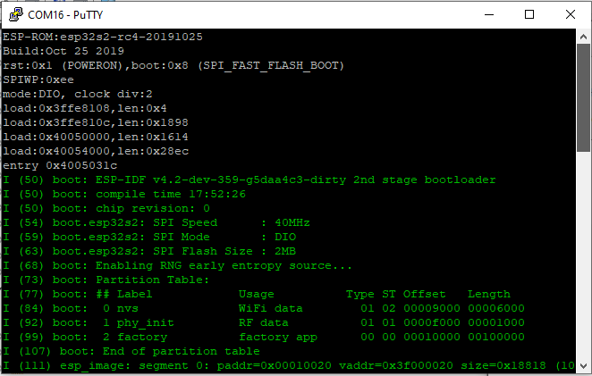
When mine starts up, it gives some basic info:


Make thanks to @unexpectedmaker for posting an informative video on the ESP32-S2 toolchain setup, including this tip on OTG pins:

ESP32-S2 USB OTG Pins   credit: @unexpectedmaker
I've adapted those notes to run my idf in WSL. There are some dependencies:

sudo apt-get install git wget flex bison gperf python python-pip python-setuptools cmake ninja-build ccache libffi-dev libssl-dev
sudo apt-get install python3 python3-pip python3-setuptools

# system-wide update to default to python3
sudo update-alternatives --install /usr/bin/python python /usr/bin/python3 10

See also the install documentation.

I also have this ESP32 install as part of my full ULX3S toolchain installer. (see upstream repo)

Thank you @i_grr for this:
One more thing, do export ESPPORT=/dev/ttyS16 once in the console session, and never have to pass -p argument to idf.py
# copy hello world
cp -r $IDF_PATH/examples/get-started/hello_world esp32-S2_hello_world

cd esp32-S2_hello_world
idf.py set-target esp32s2
idf.py menuconfig
Apparently the menuconfig will assign settings only to this project (again, thank you @unexpectedmaker for the informative video!)

To build:

idf.py build

To flash:

idf.py -p /dev/ttyS16 -b 921600 flash

To monitor (the command-line equivalent of putty):

idf.py -p /dev/ttyS16 -b monitor

Ctrl-[ to cancel

See An Introduction to Modern CMake

more to come...

Saturday, March 14, 2020

RISC-V on the ULX3S with LiteX

Today is ULX3S Campaign Launch Day on Crowd Supply!!

As I write this, funding is at 40% in just the first hour!

In pursuit of my ongoing quest to get Circuit Python working on my ULX3S.... I decided to try out LiteX. I wasn't able to get the rxrbln picorv32 picosoc for ULX3S working (yet) due to some missing files that have not yet been checked in. Part of the journey is simply figuring out which working components to use.

LiteX is included in my full toolchain build for the ULX3S (see my prior blog).

Full ULX3S toolchain directory list
Once everything is installed (OMG, it takes the better part of a day)... we can get started.

First: if you are considering getting your own ULX3S from the upcoming Crowd Supply campaign, be aware that only the larger 45F and 85F versions are available options (and capable?) of running the LiteX VexRiscv.

Some key terminology from timvideos to get started: Gateware (as in Field Programmable Gate Array) is the stuff that gets loaded onto the FPGA. Firmware is the application code that the soft CPU will execute. The BIOS is bootstrapping code baked into FPGA.

Note that I installed my development toolchain on WSL Ubuntu. I've also tested the install multiple times on VM's with real Ubuntu. But here, my blog is about using WSL, so all of my stuff is installed on my local C:\workspace directory, or from WSL's perspective: /mnt/c/workpace. On a real Ubuntu machine, simply replace that with your own ~/workspace/ directory.

Why didn't I just put my workspace in the WSL ~/workspace directory instead? Well for one, I can completely wipe out WSL and reinstall, and all my Windows workspace files are still there. I can also access those files easily from Windows and Visual Studio in particular. I'm still waiting on WSL2 (only available to Windows insider / preview at this time, which I chose not to sign up for) - and I believe I need to rip & replace for that version.

LiteX is a code generator. Not only does it create Verilog, but also a bash script to run yosys / nextpnr / ecppack to actually generate an ECP5 FPGA bit file. The fact that it can generate code to build a complete soft CPU is frankly astonishing.

Run the ulx3s.py for the respective device:
cd /mnt/c/workspace/litex-boards/litex_boards/targets
# ./ulx3s.py --device LFE5U-45F
./ulx3s.py --device LFE5U-85F
It is not super intuitive where files end up. There's certainly not a lot of documentation for the litex-boards repo. I searched in powershell:
Get-ChildItem -Recurse | Where-Object { $_.LastWriteTime -ge "03/08/2020 4:00pm" }
the top.bit file ended up in:
C:\workspace\litex-boards\litex_boards\targets\soc_basesoc_ulx3s\gateware
So from WSL it can be loaded onto the ULX3S like this:
# make sure nothing is using the ULX3S, including VM's, terminal sessions in putty, etc!
cd /mnt/c/workspace/litex-boards/litex_boards/targets/soc_basesoc_ulx3s/gateware

/mnt/c/workspace/ulx3s-examples/bin/ujprog.exe top.bit
Note how Windows executables can be called from the WSL prompt. The same command can be used in a DOS window:
# make sure nothing is using the ULX3S, including VM's, terminal sessions in putty, etc!
c:
cd \workspace\litex-boards\litex_boards\targets\soc_basesoc_ulx3s\gateware

c:\workspace\ulx3s-examples\bin\ujprog.exe top.bit
Stupid things to be aware of: the serial port is running at 11500 8N1. Don't ask me how much time I wasted when using a putty saved connection for the COM port preset at 19200 and kept wondering why there was no response when trying to connect. I don't think I'll ever make that mistake again. lol

There's also an interesting bios.bin file in
C:\workspace\litex-boards\litex_boards\targets\soc_basesoc_ulx3s\software\bios
My script for synthesizing the CPU ended up in:
/mnt/c/workspace/linux-on-litex-vexriscv/build/ulx3s/gateware/build_top.sh
I had found that build_top.sh file prior to realizing ulx3s.py accepted a device parameter. I  have two ULX3S devices, the 12F and the 85F. Guess which one is the defined default for the LiteX build? Yup, the 45F. Did I mention if things are too easy it's no fun? At first I manually edited the build file (note the above call to ulx3s.py does everything, including synthesizing the FPGA VexRiscv core). The default looks like this:
# Autogenerated by LiteX / git: e801dc02
set -e
yosys -l top.rpt top.ys
nextpnr-ecp5 --json top.json --lpf top.lpf --textcfg top.config --45k --package CABGA381 --speed 6 --timing-allow-fail
ecppack top.config --svf top.svf --bit top.bit
Ok, so one of the parameters looks easy enough. Ooph, but what about the "CABGA381"? Well, a quick google search and it turns out that's just a package specification. See the prjtrellis devices.json for a list of all of them. I'll assume that I each of the ECP5 options on the ULX3S will use the same package, and simply change the "45k" to "85k".

There are some bios docs.

Constraint (pin-level) implementation details can be found in platforms/ulx3s.py.

As shown in the ulx3s.py platform file, there's no Ethernet port configured and the serial port is configured for ECP5 pins L4 and M1:

    ("serial", 0,
        Subsignal("tx", Pins("L4"), IOStandard("LVCMOS33")),
        Subsignal("rx", Pins("M1"), IOStandard("LVCMOS33"))
    ),
To build the binaries:

cd $WORKSPACE/litex-boards/litex_boards/targets

./ulx3s.py --device LFE5U-85F --cpu-type picorv32

cd $WORKSPACE/litex-boards/litex_boards/targets/soc_basesoc_ulx3s/gateware

# to program the FPGA as a CPU:
$WORKSPACE/ulx3s-examples/bin/ujprog.exe top.bit

cd /mnt/c/workspace/litex-boards/litex_boards/targets/soc_basesoc_ulx3s/software/bios

litex_term --serial-boot --kernel bios.bin /dev/ttyS15

More to come... see my next blog: ULX3S RISC-V with LiteX - Part 2.


Sunday, March 8, 2020

RISC-V Circuit Python on ULX3S starting with the Hacker FOMU as an example

Some notes on setting up a soft RISC-V CPU to run Circuit Python.

I started with the ambitious idea of wanting Circuit Python to work on the Radiona ULX3S. Easily said...

Really short TL;DR this ended up being mostly a blog about the (mysteries and difficulties of installing) toolchain. See this to get started.

TL;DR; Circuit Python is a "C" app that needs a CPU to run on. The Feather M0 is an ARM processor option known to work well with Circuit Python.  We'll need to configure the ECP5 FPGA to be a soft CPU on the ULX3S, as Circuit Python no longer supports the current ESP32 as of version 4, but the ESP32-S2 will be supported. Fomu is an FPGA that's had some work towards Circuit Python. There are multiple Fomu versions. Need to first install foboot. Then the rxrbln fork of Claire Wolf's RISC-V toolchain for the ULX3S ECP5. Note make -j$(nproc) build-tools installs all 4 toolchains, when we probably only want riscv32i. There's an open Adafruit issue regarding Fomu port of CircuitPython #2604. Be careful using a hub. Install FPGA toolchain; see this gist and this repo. Note that 4GB is now the minimum RAM to build prjtrellis, 5GB to build nextpnr-ecp5, and at least 30GB disk.

First, I'd like to extend my thanks to Tim "mithro" Ansell for giving me a pair of Hacker Fomu's at Hackaday 2019. I'm so glad I had a chance to meet him. What an awesome guy!

Many of my notes here are quite similar to my previous, multi-part post on setting up a RISC-V on the tinyFPGA-BX.  See also Luke's picosoc example code here.

There are multiple FOMU versions. My FOMU that I received from Tim looks like this and is the hacker version, using the bash command export FOMU_REV=hacker:


The Adafruit FOMU (#4332) is the production version:


I started following along the timvideos getting started but didn't have a lot of success.

The tutorial references and links to foboot 1.8.1 (evt-installable.dfu) I eventually noticed in the list of releases and a note that the Hacker version did not have support until Version 1.8.8. Of course it didn't. No fun if it's too easy. :)


I also ordered an even more robust, known-good CircuitPython board, the Adafruit Feather M0 Express. This started me down yet another rabbit hole (specifically this) as the fomu didn't play well when sharing a USB hub.

Also - in my case, for some reason the Ubuntu VM no longer had an IP address after rebooting the host. Apparently others have had the same problem. Indeed I needed to add this to my /etc/network/interfaces after confirming ens33 was the name of my network adapter with the ip address command. Nothing is ever as easy as it is supposed to be. The fun never stops! ;)


# The primary network interface
auto ens33
iface ens33 inet dhcp
confirm that ens33 is the proper device.

Update: it seems that Ubuntu only "forgets" the IP address assignment if the VM is paused. During reboots or initial install - the network interface works properly with no edits to the interface file.

Oh - and more that the default 20GB disk space is needed (40GB is safe, but perhaps as little as 35GB) if doing this in a VM. Ubuntu does not automatically recognize a bigger disk after it has been expanded, so gparted needs to be installed as explained on stackexchange. Simply right-click and select "Resize/Move". Be sure to click on the little green check mark to apply changes.


cd ~

# does dfu-util work?
dfu-util -l

# if "Cannot open DFU device 1209:5bf0" try sudo
sudo dfu-util -l

# can't find dfu-util with sudo?
whereis dfu-util

# here we go
sudo /home/gojimmypi/ecp5-toolchain-linux_x86_64-v1.6.2/bin/dfu-util -l

# upgrade foumu
cd workspace
mkdir fomu
cd fomu
wget https://github.com/im-tomu/foboot/raw/master/releases/v1.8.1/evt-installable.dfu
sudo /home/gojimmypi/ecp5-toolchain-linux_x86_64-v1.6.2/bin/dfu-util -D evt-installable.dfu

If successful, should give output like this:

dfu-util 0.9

Copyright 2005-2009 Weston Schmidt, Harald Welte and OpenMoko Inc.
Copyright 2010-2019 Tormod Volden and Stefan Schmidt
This program is Free Software and has ABSOLUTELY NO WARRANTY
Please report bugs to http://sourceforge.net/p/dfu-util/tickets/

Match vendor ID from file: 1209
Match product ID from file: 5bf0
Opening DFU capable USB device...
ID 1209:5bf0
Run-time device DFU version 0101
Claiming USB DFU Interface...
Setting Alternate Setting #0 ...
Determining device status: state = dfuIDLE, status = 0
dfuIDLE, continuing
DFU mode device DFU version 0101
Device returned transfer size 1024
Copying data from PC to DFU device
Download [=========================] 100%       106814 bytes
Download done.
state(7) = dfuMANIFEST, status(0) = No error condition is present
state(8) = dfuMANIFEST-WAIT-RESET, status(0) = No error condition is present
Done!

To more gracefully setup permissions see the fomu docs. Basically:
# add this line to /etc/udev/rules.d/99-fomu.rules
SUBSYSTEM=="usb", ATTRS{idVendor}=="1209", ATTRS{idProduct}=="5bf0", MODE="0664", GROUP="plugdev"

And then:

sudo groupadd plugdev
sudo usermod -a -G plugdev $USER
id $USER
sudo udevadm control --reload-rules
sudo udevadm trigger

# logoff then back on


Next, we want to have the rxrbln ULX3S version of PicoRV32:
# on a completely new system:
THISRISCV=riscv32i
THIS_RISCV_PATH=/opt/$THISRISCV/bin
MIN_ULX3S_MEMORY=5050000

if [ $(free | grep Mem | awk '{ print $2 }') -lt $MIN_ULX3S_MEMORY ]; then
  echo ""
  echo "System memory found:"
  free
  echo ""
  read -p "Warning, at least $MIN_ULX3S_MEMORY bytes of memory is needed. Press$
fi


sudo apt-get update --assume-yes 
sudo apt-get upgrade --assume-yes
sudo apt-get install git --assume-yes

cd ~
mkdir -p ~/workspace
cd workspace

git clone https://github.com/rxrbln/picorv32.git

cd picorv32

sudo apt-get install make        --assume-yes
sudo apt-get install make-guile  --assume-yes
sudo apt-get install libgmp3-dev --assume-yes
sudo apt-get install libmpfr-dev --assume-yes
sudo apt-get install libmpc-dev  --assume-yes

sudo apt-get install autoconf automake autotools-dev curl libmpc-dev \
        libmpfr-dev libgmp-dev gawk build-essential bison flex texinfo \
    gperf libtool patchutils bc zlib1g-dev git libexpat1-dev --assume-yes


make download-tools

# install *all four* riscv flavor toolchains:
# make -j$(nproc) build-tools

# or install only riscv32i:
sudo mkdir /opt/riscv32i
sudo chown $USER /opt/riscv32i

git clone https://github.com/riscv/riscv-gnu-toolchain riscv-gnu-toolchain-rv32i
cd riscv-gnu-toolchain-rv32i
git checkout 411d134

# if you see fatal: clone of 'git://  ... 
# users sitting behind a firewall may need these:
git config --global url.https://github.com/.insteadOf git://github.com/
git config --global url.https://git.qemu.org/git/.insteadOf git://git.qemu-project.org/
git config --global url.https://anongit.freedesktop.org/git/.insteadOf git://anongit.freedesktop.org/
git config --global url.https://github.com/riscv.insteadOf git://github.com/riscv

# this next statement takes a long time. be patient:
git submodule update --init --recursive

mkdir build; cd build
../configure --with-arch=rv32i --prefix=/opt/riscv32i
make -j$(nproc)

# see if it is working:
/opt/riscv32i/bin/riscv32-unknown-elf-gcc --version

# add to path
if [ "$(cat ~/.bashrc | grep  $THIS_RISCV_PATH)" == "" ]; then
  echo PATH=$PATH:$THIS_RISCV_PATH >> ~/.bashrc
  echo "~/.bashrc updated with this line:"
  echo PATH=$PATH:$THIS_RISCV_PATH
else
  echo "Found $THIS_RISCV_PATH in ~/.bashrc - path not changed."
fi

if [ "$(echo $PATH | grep  $THIS_RISCV_PATH)" == "" ]; then
  export PATH=$PATH:$THIS_RISCV_PATH
  echo "Updated current path: $PATH"
else
  echo "Path not updated. PATH=$PATH"
fi

cd ~/workspace
git clone https://gist.github.com/gojimmypi/f96cd86b2b8595b4cf3be4baf493c5a7 ulx3s_fpga_toolchain
cd ulx3s_fpga_toolchain
chmod +x ULX3S_WSL_Toolchain.sh
./ULX3S_WSL_Toolchain.sh


Run scripts with the source command if you don't want to start a new shell, or manually set path. You may wish to put this line at the end of your ~/.bashrc file:
#add path to riscv32i compiler
PATH=/opt/riscv32i/bin:$PATH

Once the RISC-V toolchain is installed, there's some sample code in the picosoc directory. Fortunately rxrbln has already made some modifications in the Makefile for the ULX3S. The C code is compiled with:

make ulx3s_fw.img


To upload the code to the ULX3S:

make ulx3sprog


Note from the Makefile there are 2 key steps: #1 to put the ulx3s.bit soft CPU onto the FPGA, then #2 put the firmware into FLASH memory:
/usr/src/f32c-ujprog/ujprog/ujprog -j FLASH -f 0x200000 ulx3s_fw.img
/usr/src/f32c-ujprog/ujprog/ujprog -t ulx3s.bit # -j FLASH 


The default install directory for ujprog is /usr/local/bin/ujprog however the rxrbln Makefile expects it to be /usr/src/f32c-ujprog/ujprog/ujprog
so we'll just create a quick symlink
sudo mkdir -p /usr/src/f32c-ujprog/ujprog/
sudo ln -s /usr/local/bin/ujprog /usr/src/f32c-ujprog/ujprog/ujprog
yosys/nextpnr/ https://gist.github.com/gojimmypi/243fc3a6eead72ae3db8fd32f2567c96


In the end, I put together a full ULX3S toolchain installer. Next blog I go into details of actually getting the soft CPU and RISC-V code onto the ULX3S.


Other stuff:

TODO - do we really want a 2+ year old RV32I toolchain? (note git checkout 411d134)


 * https://workshop.fomu.im/en/latest/

See also:

A cobbled-together profiler for CircuitPython.

Sunday, February 23, 2020

Raspberry Pi - pi-hole setup notes

In the category of "why didn't I do this sooner" - I finally setup my full network ad-blocking pi-hole. It's great! I can't believe I waited this long. The install is really quite straightforward for a basic system, however there are always options for fine tuning.

The basic install is quite good and blocks quite a bit of junk.

One of the places that has more extensive information on pi-hole options is this smart home beginner article, which ironically also features a ton of ads that are not blocked by a pi-hole default install. :/

When considering which device to run pi-hole on, consider the requirements. It does not have to be a Raspberry Pi, although that's nearly a perfect platform for most users. I ended up choosing a prior-generation Raspberry Pi 3 Model B+ for the lower power consumption and a Samsung 32GB microSDHC EVO, purchased separately.  Given my actual requirements, I probably should have chosen the Raspberry Pi 2, instead. (see below on power details)

My Raspberry Pi 3B+ has built-in WiFi and Bluetooth. Both are features that I will not likely use for my pi-hole. I prefer the reliability (and security) of a wired Ethernet connection for something as important as DNS lookups.

One of the benefits of the 3B+ is that the official Raspberry Pi PoE HAT can be used to power the Raspberry Pi over Ethernet. I didn't go this route.

Update: see my blog on Raspberry Pi Headless Setup. I've found setting up those 4 pre-configured files and copying them to the root of SD card at image-write-time is quite handy and gets the RPi basically operational with minimal fuss.

A key detail is to edit the config.txt file on the root of SD card (found in /boot/config.txt once RPi is running) before inserting into the RPi; add this line to allow serial TTL communication and avoid needing to plug in a monitor and keyboard for initial setup:

enable_uart=1

Note that despite having 5V pins right next door, the Raspberry Pi serial port uses 3.3V logic.

Connect your favorite USB to TTL Serial cable:
Raspberry Pi pinout showing Serial TTL from raspberrypi.org docs
Then login with putty or some other terminal program. For more detailed information on setting up a headless Raspberry Pi, see this sparkfun how-to.

I prefer to run sudo raspi-config to do things like:
  • Assign password
Network Options:
  • assign host name such as "pi-hole"
Localisation Options:
  • Change the locale to en_US.UTF-8 UTF-8
  • Change timezone to Pacific Time
Interfacing Options:
  • Disable Camera
  • Enable SSH
  • Disable VNC
  • Disable SPI
  • Disable I2C
  • Enable Serial
  • Disable 1-Wire
  • Disable Remote GPIO
Advanced Options:
  • Expand Filesystem 
  • GPU Memory Split set to 16
Update raspi-config to the latest version.

Next assign a static IP address via sudo nano /etc/dhcpcd.conf and add these lines:

interface eth0
        static ip_address=192.168.1.77/24
        static routers=192.168.1.254
        static domain_name_servers=127.0.0.1

Put in your values for device IP address, router, and actual DNS (needed for initial install) . After setting up the pi_hole, set the DNS to 127.0.0.1 as shown.

Disable IPV6 unless you know you need it. Edit /etc/sysctl.conf and put these lines at the bottom:
net.ipv6.conf.all.disable_ipv6 = 1
net.ipv6.conf.default.disable_ipv6 = 1
net.ipv6.conf.lo.disable_ipv6 = 1
net.ipv6.conf.tun0.disable_ipv6 = 1


One of the main problems with the Raspberry Pi is the continual writing to the SD card and subsequent (lack of) reliability when in operation for years. See the log2ram install, below, that can help with this. Hackaday also has an article on the coolness of log2ram that refers to this log2ram blog by Erich Styger.

Next, main setup:

# system update
sudo apt-get update && sudo apt-get upgrade

# install essentials
sudo apt-get install git
sudo apt-get install fail2ban
sudo apt-get install dnsutils
sudo apt-get install arpwatch
sudo apt-get install iptables-persistent

# remove things that will not be used:
sudo apt-get purge realvnc-vnc-server --assume-yes

# basic pi-hole install
cd ~/
git clone --depth 1 https://github.com/pi-hole/pi-hole.git
cd "pi-hole/automated install/"
sudo bash basic-install.sh
sudo pihole -a -p

# log2ram install (optional)
cd ~/
curl -Lo log2ram.tar.gz https://github.com/azlux/log2ram/archive/master.tar.gz
tar xf log2ram.tar.gz
cd log2ram-master
chmod +x install.sh && sudo ./install.sh
# REBOOT BEFORE INSTALLING ANYTHING ELSE

This might be a good time to set that static domain_name_servers=127.0.0.1 setting.

Operational check for log2ram:

# not blank if working properly:
mount | grep log2ram

# not blank if working properly:
df -h | grep log2ram

If it appears the log files need more space, edit the /etc/log2ram.conf
.
See firewall notes for supported operating systems. Secure the RPi with IP Tables (optional):

# Flush the tables to apply changes
sudo iptables -F
sudo ip6tables -F

# Default policy to drop everything but our output to internet
sudo iptables -P FORWARD DROP
sudo iptables -P INPUT   DROP
sudo iptables -P OUTPUT  ACCEPT

# do the same for IPv6
sudo ip6tables -P FORWARD DROP
sudo ip6tables -P INPUT   DROP
sudo ip6tables -P OUTPUT  ACCEPT

# Allow established connections (the responses to our outgoing traffic)
sudo iptables -A INPUT -m state --state ESTABLISHED,RELATED -j ACCEPT

# Allow IPv6 established connections (the responses to our outgoing traffic)
sudo ip6tables -A INPUT -m state --state ESTABLISHED,RELATED -j ACCEPT

# Allow local programs that use loopback (Unix sockets)
sudo iptables -A INPUT -s 127.0.0.0/8 -d 127.0.0.0/8 -i lo -j ACCEPT

# allow incoming SSH/SCP conections to this machine from 192.168.1.0/24 only
sudo iptables -A INPUT -s 192.168.1.0/24 -p tcp --dport 22 -m state --state NEW -j ACCEPT

# In case a Windows drive is mapped, uncomment this line:
# sudo iptables -A INPUT -s 192.168.1.0/24 -p tcp --dport 445 -m state --state NEW -j ACCEPT

# pi-hole ports
iptables -I INPUT 1 -p tcp -m tcp --dport 80 -j ACCEPT
iptables -I INPUT 1 -p tcp -m tcp --dport 53 -j ACCEPT
iptables -I INPUT 1 -p udp -m udp --dport 53 -j ACCEPT
iptables -I INPUT 1 -p tcp -m tcp --dport 67 -j ACCEPT
iptables -I INPUT 1 -p udp -m udp --dport 67 -j ACCEPT
iptables -I INPUT 1 -p tcp -m tcp --dport 4711 -i lo -j ACCEPT

# save iptables to be in place after a reboot
sudo /sbin/iptables-save > ~/iptables.txt
sudo cp ~/iptables.txt /etc/iptables/rules
iptables-persistent
iptables --list


To make the IP Table changes stick, I chose iptables-persistent

See also: Linux Iptables: How to specify a range of IP addresses or ports.

If your pi-hole sits on a different network then all traffic it "sees" will appear to come from a single router IP address.

Some people may be interested in unbound recursive DNS server solution (see also this how-to). I didn't initially have much luck with it, and in fact I later saw my first system crash on a different Raspberry Pi within 24 hours of installing it.

Once everything is setup, there are MANY more lists to make the pi-hole even better. Thanks Jermal Smith for suggestions on other lists to block from his pi-hole blog.

For more information on manually adding domains, see the pihole command. Local lists can be appended by using the FILE:// syntax, although the data in that file does not seem to be successfully added to block list. No warning or other message is given:


file://c:/download/pi-hole/my_block_list.txt

Yet after refresh, the entry is not in the block domain list search:


So perhaps a GitHub gist is a better home for custom lists.

To add a large list of lists, such as this one from Jermal Smith, simply add them to the respective /etc/pihole/adlists.list on the pi-hole. Be sure to include only URL's and not the title text in the first line.

Some essentials that I needed to whitelist:


aka.ms - used for Visual Studio updates


A final fine-tuning: See the Raspberry Pi Power Requirements. It's a shame to waste standby power for things not being used. Note that the Raspberry Pi 3 Model B+ I chose typically uses 500mA. In contrast, the Raspberry Pi 2 uses only 350mA, Part of the difference is the on-board WiFi and Bluetooth capabilities.

These can be manually turned off:


sudo iwconfig wlan0 power off
This can be added to /etc/rc.local. Also consider editing /etc/modprobe.d/raspi-blacklist.conf as noted in the forum topic:


#wifi
blacklist brcmfmac
blacklist brcmutil
#bt
blacklist btbcm
blacklist hci_uart

or

# ref: https://www.raspberrypi.org/forums/viewtopic.php?f=63&t=138610
# bluetooth
blacklist hci_uart
blacklist btbcm
blacklist btintel
blacklist rfcom
blacklist btqca
blacklist btsdio
blacklist bluetooth


And edit the /boot/config.txt:


dtoverlay=pi3-disable-wifi
dtoverlay=pi3-disable-bt


Note the 1000BaseT has a higher power requirement.

My Raspberry Pi operates at about 50°C; (specs qualified from -40°C to 85°C)

For more information, see the pi-hole discourse.

Sunday, February 16, 2020

C# on the Radiona ULX3S using the nanoFramework dotnet CLR

It has been over a year since I first learned about the Radiona ULX3S development board. This is the perfect "crossover" board that has appeal for developers interested in electronics, FPGA development, and even just regular software development. With both an Espressif ESP32 and the Lattice ECP5, along with a ton of peripherals and GPIO pins - there's something for everyone here.

Radiona ULX3S from https://radiona.org/ulx3s/
The ULX3S is coming soon to CrowdSupply!

If you just want to get started with C#, see my notes here or visit docs.nanoframework.net.

A lot has changed since I first heard the name Espressif way back in 2015 and ordered this thing called a "Diymall® Esp8266 Esp-12e Serial Wifi Wireless Transceiver Module for Arduino UNO 2560 R3 Nano" from Amazon. Ooph. What a name.


And what an ordeal it was to get that device going... I remember the convoluted process of manually holding some GPIO pin low while it powered up, and then releasing another, all with level-shifting the 5V USB-TTL on a rats-nest breadboard of jumper wires.  The "excitement' was seeing the old modem-style "AT" command prompt. Admittedly, it was pretty cool. How really surreal that was - to see the Hayes-like AT prompt for a WiFi device.

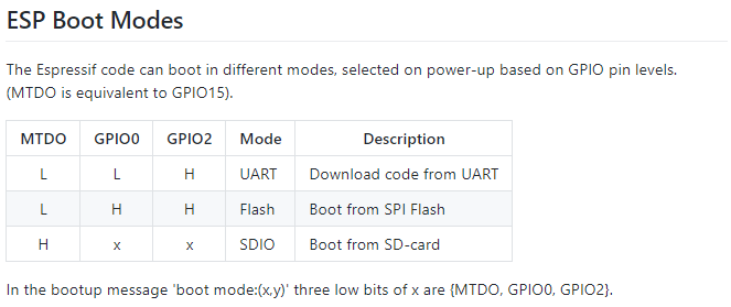
ESP Boot Modes from the ESP8266 WiKi

Indeed it seemed interesting to have modem-like commands available in such a small and inexpensive package (who knows what it would take to actually send and receive WiFi packets with AT commands!). The documentation was pretty bleak and ridiculously incomplete at the time.

Fast forward just 5 years (that's 103 in technology years) - and Espressif continues to amaze with awesome documentation and ridiculously inexpensive hardware. And the languages! I've not seen an AT prompt on any of my devices for a long time. Starting with Lua on the ESP8266, the tech community soon realized that other languages could be implemented on the Espressif hardware. Of  course, C/C++ was the first and most obvious choice for embedded devices. But then something really crazy came along: MicroPython on the inexpensive ESP8266 WiFi device. Just a few months after seeing that first AT prompt, I backed the MicroPython on the ESP8266 crowd funding project. One thing led to another and now there are many languages available, and of course the next gen ESP32 hardware platform. It was when looking at the languages on the ESP32 Wikipedia page, of all places - that I learned about a truly amazing language capability: C# on an embedded device!

I've been programming C/C++ on and off over the course of many years. At the Day Job however, my focus these days is on C# in the Visual Studio environment. That's where I am probably most comfortable and the most productive. For programming "Arduino Style" C/C++ on embedded devices, my go-to tool has been the Visual Micro add-in extension for Visual Studio. With hundreds of thousands of downloads and a solid 5 star rating, I'm clearly not alone in liking Visual Micro. I've mentioned them numerous times in prior blogs, such as this one for the ULX3S.


If you've never used the Visual Micro extension, I highly recommend giving it a try.

Back to the topic of this blog. C#. On. an. embedded. device. WOW! As mentioned above, I originally learned of this capability on the Wikipedia page. There's also a reference on the Espressif web site with a relatively simple name of "nanoFramework":

"Developers can harness the powerful and familiar Microsoft Visual Studio IDE and their .NETC# knowledge to quickly write code without having to worry about the low-level hardware intricacies of a microcontroller. Desktop .NET developers will feel “at home” and are able to use their skills in embedded systems development, enlarging the pool of qualified embedded developers. It includes a reduced version of the .NET Common Language Runtime (CLR) and features a subset of the .NET base class libraries along with the most common APIs included in the Universal Windows Platform (UWP) allowing code reuse from desktop applications, IoT Core applications, thousands of code examples and open source projects. Using Microsoft Visual Studio, a developer can deploy and debug the code directly on real hardware." --Espressif Systems
Ok, so C# on an embedded device is amazing in itself. If you've read some of my prior blogs, you've seen my interest in single-step JTAG debugging the Espressif chips. The ESP8266 in particular can be quite difficult, depending on the vendor. Still, even with JTAG working, I've never been able to get the real experience of full debugging as seen in Visual Studio with high-level language debugging, or even the Atmel Studio with the Atmel ICE for their chips.

Enter nanoFramework. This is one of the most amazing implementations I've seen in quite some time. They have the .Net CLR on an embedded device! Not just the CLR, but the fully integrated Visual Studio debugging, single-step, hover-text values and more. Getting started is pretty straightforward: first step of course is to install the nanoFramework extension from the Visual Studio Marketplace. Note there are two flavors: the nanoFramework for VS2017 and a preview nanoFramework for VS2019.

I do think their instructions are a bit overly complicated for the first time user. For one - compiling the entire framework is certainly not required to program C# on your device, yet it is featured front and center on the getting started page. I have some notes of my own on Programming the ULX3S ESP32 using C# in Visual Studio. Basically the firmware needs to be uploaded to the device, then Visual Studio needs to connect with Device Explorer.

I tweeted this video of single-step blinky in C# to show single step in action.

Beyond blinky, I was curious as to what else could be done with this framework. So how about a simple "Hello World" printed on the screen? Ha! What a twisty little passage all alike rabbit-hole that turned out to be.

First, I discovered there's currently no direct support of the SSD1331 SPI display that I am using with the ULX3S. However, there are plenty of Arduino-style libraries out there. Hm. Arduino libraries... ah yes, it is one thing to be able to write code, it is another issue altogether to actually be able to leverage the existing libraries for peripherals. All the open source code out there that allows the ESP32 to use Ardunio libraries has certainly helped the self-sustaining fire of maker interest and development. But what about C#?

I started out in the #Targets-ESP32 thread on the nanoFramework Discord. Yes, they need multiple threads for different platforms, as they also have C# working on STM32,  TI CC13x2, CC26x2, CC32xx, and NXP MIMXRT1060_EVAL boards! As my issue was not ESP32 specific, they kindly referred me to the #UI thread (UI meaning "display hardware", not the UI of the nanoFramework extension in Visual Studio). It is there that I learned a lot of great information from some clearly talented developers that very kindly and patiently answered my newbie questions.

I only recently started using Discord. I think I like gitter channels more, but both seem to be weak for linking to specific comments of interest. Part of this blog is for me to gather up the key tidbits all in one place. Be sure to check out the ULX3S gitter channel, too.

I learned quite a bit about the SSD1331 display during a exchange with emard in ULX3S issue #8. For the nanoFramework here I started with a known-working project, my ULX3S Visual Micro SSD1331 Display Example. In particular, the key pin numbers:

// working ULX3S  
#define oled_csn  17 // aka cs - chip select
#define oled_dc   16 // aka ds aka a0 -  SPI data or command selector pin
#define oled_resn 25 // aka rst - reset
#define oled_mosi 15 // aka mosi - data
#define oled_clk  14 // aka sclk - clock
#define oled_miso -1 // 12 not used

from the FPGA perspective:

N2 to N3 for oled_csn /CS  to wifi_gpio17 (GPIO17)
P1 to L1 for oled_dc /DC   to wifi_gpio16 (GPIO16)
P2 to E3 for oled_resn/RES to wifi_gpio25 (GPIO25)
P3 to J1 for oled_mosi/SDA to sd_cmd      (GPIO15)
P4 to H2 for oled_clk /SCL to sd_clk      (GPIO14)

See also this code on the espressif/arduino-esp32 repo for VSPI and HSPI initialization and pins:


void setup() {
  //initialise two instances of the SPIClass attached to VSPI and HSPI respectively
  vspi = new SPIClass(VSPI);
  hspi = new SPIClass(HSPI);
  
  //clock miso mosi ss

  //initialise vspi with default pins
  //SCLK = 18, MISO = 19, MOSI = 23, SS = 5
  vspi->begin();
  //alternatively route through GPIO pins of your choice
  //hspi->begin(0, 2, 4, 33); //SCLK, MISO, MOSI, SS
  
  //initialise hspi with default pins
  //SCLK = 14, MISO = 12, MOSI = 13, SS = 15
  hspi->begin(); 
  //alternatively route through GPIO pins
  //hspi->begin(25, 26, 27, 32); //SCLK, MISO, MOSI, SS

  //set up slave select pins as outputs as the Arduino API
  //doesn't handle automatically pulling SS low
  pinMode(5, OUTPUT); //VSPI SS
  pinMode(15, OUTPUT); //HSPI SS

}

I tried to use the existing SPI capabilities of the nanoFramework, but I was unable to get the display to cooperate. Nothing happened. But why?

This is where more serious hardware debugging tools are needed. One method I used in the past to debug some serial port communication problems - involved a Digital Storage Oscilloscope (in my case, a Rigol DS1054z). Even though that one is relatively small as oscilloscopes go, it was at my workbench and I was working at the kitchen table (and ok, the workbench needs to be cleaned up an organized). Not only inconvenient, but also perhaps not the most practical (power cord, size, etc). Although my serial decoding was an interesting exercise on the oscilloscope - what I really needed is a logic analyzer.

It was well over 5 years ago that I first started using the Saleae logic analyzer software. The cool thing here is that it is a computer-based debugging tool. Whereas the oscilloscope is an oscilloscope all on its own, complete with its own power cord and display - the Saleae is just a USB peripheral. It doesn't even have a wall-wart power supply: just a USB connection and logic probes.

Sure enough - after a ridiculously long time trying to figure out the display problem with software, the logic analyzer instead made the problem abundantly obvious: nothing was happening as the D/C (data command) pin. I was hoping that somehow the SPI driver would have just "known" how to control the bus for the display during NativeInit. Silly me. Of course not. Nope.


I opened this issue to implement more flexible SPI pin definitions, in particular something to manage that D/C pin. @AdrianSoundy responded with:
"The DC and Reset pins are not part of the SPI bus. They are specific to the displays. You have to create separate gpio pins for those functions."
Hm. Well, yes, I guess that is technically true. Still, I wanted to see if I could get my SPI  display to work in C#, so I took the advice and wrote my own DC-pin-controlling code to manage the data/control line, and let the native drivers handle the actual data transfer.

I created this nanoFramework SSD1331 example to manually bit-bang the SPI bus. As of the date of this blog, there's not a lot there. I leveraged the Adafruit SSD1331 C++ library to create my own limited C# OLED SSD1331 class library. I also created another class library project, this one an Arduino-style nanoFramework "pins" helper to allow the use of the familiar pinMode and digitalWrite functions when converting the Adafruit library to C#.

It is a bit of a mess at the moment, but it does have the capability of initializing the display and poking some pixels into place. It doesn't sound like much - but again, doing this from C# in Visual Studio is what made it really quite cool. I had this little victory tweet at the end of that weekend:


Drawing a line is one thing... drawing it quickly, well that's another. After the excitement had warn off (ok, it was just a blue line)... I realized just how slowly the pixels were being drawn. Why? Did I mention the little twisty passages? Yes, this rabbit hole goes much deeper.

To start, let's go back to the known-working SPI display example. See also this blog where I go into more detail with that example.

Again, there's nothing like a logic analyzer to see what's going on with the voltage levels of ones and zeros on the wires. Looking at the source code, the SPI bus for the display gets interesting at startup time, or specifically during Adafruit_SSD1331::begin - where initialization bytes are sent to the display:


void Adafruit_SSD1331::begin(uint32_t freq) {
    initSPI(freq, SPI_MODE0);

    // Initialization Sequence
    sendCommand(SSD1331_CMD_DISPLAYOFF);   // 0xAE
    sendCommand(SSD1331_CMD_SETREMAP);          // 0xA0
#if defined SSD1331_COLORORDER_RGB
    sendCommand(0x72);    // RGB Color
#else
    sendCommand(0x76);    // BGR Color
#endif
    sendCommand(SSD1331_CMD_STARTLINE);  // 0xA1
    sendCommand(0x0);
    sendCommand(SSD1331_CMD_DISPLAYOFFSET);  // 0xA2
    sendCommand(0x0);
    sendCommand(SSD1331_CMD_NORMALDISPLAY);   // 0xA4
    sendCommand(SSD1331_CMD_SETMULTIPLEX);  // 0xA8
    sendCommand(0x3F);     // 0x3F 1/64 duty
    sendCommand(SSD1331_CMD_SETMASTER);   // 0xAD
    sendCommand(0x8E);
    sendCommand(SSD1331_CMD_POWERMODE);   // 0xB0
    sendCommand(0x0B);
    sendCommand(SSD1331_CMD_PRECHARGE);   // 0xB1

...etc


This is where I had a chance to try out my new Saleae logic analyzer. It's funny how once you buy something, you start noticing other people that have that same "thing". I noticed that @GregDavill had posted something on Twitter with his Saleae - and so I commented on it. His reply was crazy! I don't think I'll be using mine as a coaster anytime soon LOL. So here's my new Saleae, sans mug, hooked up to my Radiona ULX3S:

ULX3S with SSD1331 display on a breadboard with Saleae Logic Analyzer
In order to most easily connect the logic analyzer, I disconnected the display from the main ULX3S board and plugged it into the breadboard. Here, I would have preferred that the Saleae had male connector pins instead of female, but a few short M-M jumpers to the rescue.

I did buy my own Dupont crimping too la few years back, so I will probably make my own Saleae male-pin probe set for breadboards. The only think needed is some wire and a Dupont header kit such as this one on ebay.

So back to the setup: Not completely intuitive is the trigger and decoding of the SPI signals. The first thing is to setup the start of capture based on the falling edge of the clock:


The next is to tell the Saleae software *which* pins are being used for decoding. First select the SPI decoder on the right side of the app:


Next, click on the little gear and "edit settings" to select which channels are which SPI pins:


The good thing is that if you don't need to change protocols, the software remembers this even after uninstalling and re-installing new software. So until you change debugging projects, the setup of the logic analyzer stays consistent.

From a software perspective, we just simply expect the bytes to be sent. But to actually see what's going on, the logic analyzer is indispensable:


Here we can see the same hex codes in the Salaea decoded from the logic analyzer probes as seen in the code segment, above. Setup of the decoder in the software was also vastly easier than the serial decoder mentioned above on my oscilloscope. The first byte sent on the SPI bus is 0xAE, the command turn turn the display off during initialization. How cool is that?

Although the Salaea software is not implemented with the proper Windows UI (banner toolbar across the top, File-Save, Help-About, etc)... for the most part it is quite easy to use and intuitive. One of the less-obvious features is that you can double click on the decoded values in the lower right, and the display auto-scrolls and auto-scales to the trace for that value. Very nice.

Once I had a benchmark of sending a byte of SPI data in under 8 micro-seconds, let's see what happens when manually bit-banging the pins from C#. Here's the code to send an SPI byte:


        private void spiWrite(byte b)
        {
            for (byte bit = 0; bit < 8; bit++)
            {
                if ((b & 0x80) > 0)
                {
                    SPI_MOSI_HIGH();
                }
                else
                {
                    SPI_MOSI_LOW();
                }
                SPI_SCK_HIGH();
                b <<= 1;
                SPI_SCK_LOW();
            }
        }


This is pretty straightforward and almost identical to the Adafruit C/C++ code in their SPITFT library (minus the hardware-specific conditional compile directives) that I based my C# code on. See also the spiWrite() in esp32-hal-spi.c.

Next, I tried to use the built-in nanoFramework SPI driver, but manually control the D/C line.


private void WriteCommand(byte command)
        {
            _buffer1[0] = command;

            // the time between the next two statements is a whopping 0.3ms
            _DS.Write(GpioPinValue.Low);
            _DS.Write(GpioPinValue.High);

            // here we manually bring DS low
            _DS.Write(GpioPinValue.Low);
            _spi.Write(_buffer1); // all 8 bits in about 54uS
            _DS.Write(GpioPinValue.High);
        }


Here's what it looks like on the logic analyzer:


Notice in particular the vastly longer delay in switching the D/C line as compared to the bits sent during the native _spi.Write(). There's nearly three-quarters of a millisecond window for the D/C line, but only about 54 microseconds to send the entire 8 bits of data:


When I posted this information on the Discord channel, @terryfogg suggested that I review a similar example being worked on. From what I could tell, it was VSPI with a different set of pins and also confirmed that C# is just too slow for this kind of, so instead this was using native code. Ah yes, the twisty little passage - the Rabbit hole goes on to another whole level: calling native code from C# on an embedded device.

The next level of complexity? Interop of course. To get started, there's a pretty good tutorial on Interop in the .Net nanoFramework. Yes, interop of course pretty much screws the entire concept of managed code, but with the benefit of vastly better performance. Hm. See the links at the bottom of this page for more information on calling unmanaged code from C#. I think that's probably a whole topic in and of itself. Stay tuned...


Full disclosure: I purchased the Saleae Logic Pro 16 at a substantial discount since I (sadly) don't do this fun stuff for a living. Saleae has a "Electronics Enthusiasts (non-commercial use)" discount. My primary motivation was the USB3 sampling speeds of up to 125MHz to be used as I dig deeper into the ULX3S FPGA capabilities. The discount of course made all the difference for my hobbyist budget. In fact, there's an "Enthusiast Discount Extreme Edition" that I hope to qualify for with this blog entry.

I purchased the ULX3S early last year from Goran after reading about it on Hackaday and sending an email. Although I am listed as one of the members of the Radiona CrowdSupply team, I am not employed by Radiona, nor do I receive any financial compensation from them.

All opinions expressed here are my own and not representative of my employer.


Resources, Inspiration, Credits, and Other Links:

Find gojimmypi at gojimmypi.github.io

I'm currently working on my new blog home at  gojimmypi.github.io After implementing a variety of features such as dark mode , syntax hi...