The more I use Visual Studio 2017 and the integration with GitHub, the more I am amazed at just how well this all works. I'll use a real-world walk-through with some Espressif ESP32 Arduino code that I am using on my M5Stack to show how really useful this is.
Hmm... interesting. But when I tried to use that, it seems to not be implemented for me:
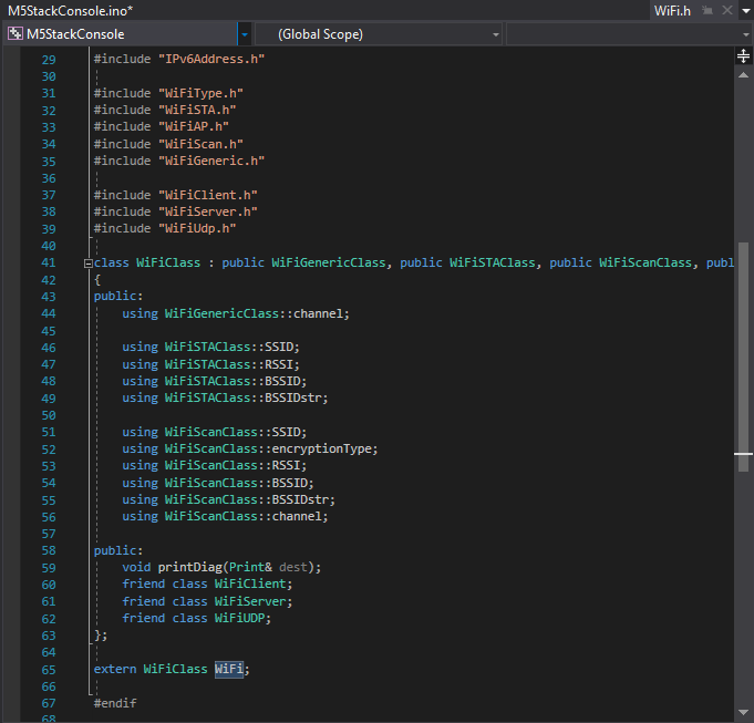
So here we can right click on WiFi and Go To Definition:
And sure enough.. the WiFi.h file opens... but as a "soft" open tab on the right, instead of the regular solution file on the left; hmm. there's no forceSleepBegin() in the header. Let's see if we can find out more.
It gets more interesting, as now we can right click on the WiFi.h tab name and select Open Containing Folder:
So here I can see which of the several (in my case Arduino or ESP32) WiFi libraries are actually being used in this project. In the path we see the ESP32 library is being referenced:
Now.. this directory was installed via a git clone command some months ago.
Even more cool, is we can right-click on Windows Explorer and Open in Visual Studio. (yes, going back!) Be sure to click on white page in the Explorer file list, and not on a specific file. Otherwise only that single file will be opened.
Note how the ~\src directory is opened in the solution. Looking closely, there are little lock symbols next to each file! I didn't do anything to set that up. It just works!
Yes, those little locks say "this is a file under source control and has not been checked out nor edited".
Next, to really see the magic, click on the Team Explorer tab (or View - Team Explorer).
Look! A Welcome to GitHub for Visual Studio message. It just knows that this subdirectory has a parent directory somewhere above that has the git clone repository information. How cool is that!?!
Click on the Sync Button/Tab and we can see the incoming commits, LIVE from GitHub!
Here we can press the Fetch link to just bring in the historical information, but not change our local files.
Want something else? Click on the master Branch text/link, to view the other branches:
Double-click to select a different branch. All the usual git commands apply, so git stash is probably your friend here. (unfortunately manually from command line, as far as I know)
Sadly, the "Search Work Items" does not seem to work for me; I cannot type anything there. That will soon be a Very Cool feature.
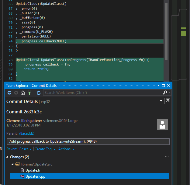
We can however, right-click on commit items and compare & see what changes by pulling each commit:
All from the comfort of the Visual Studio UI. How really awesome is that!?! :)
Close the yellow welcome message banner and we can see exactly where this repository lives on GitHub. Press the little home icon any time in Team Explorer to return to this view:
Click on the repository link and the GitHub web page for the repository (in this case Espressif Aduino repository on GitHub) opens in your default browser.
As a suggestion, there are probably some files that should be added to your .gitignore file. Simply going though this exercise creates some files that you probably don't want to push back to the repository and may interfere with pulls. Click the Changes tab/button on the Team Explorer home to see what's been added:
These will of course interfere with selecting other branches, etc.
Overall this is really quite cool. The developers creating Visual Studio simply rock. :)
Today I'm trying to use the AVR serial port on a custom ATMEGA328 board.
TL;DR
Know your fuse settings! Incorrect settings can result in timing problems, including incorrect UART baud rates.
RS232 Serial port UART decoding using Rigol DS1054z Oscilloscope
How to fix bad baud rate timing with software.
Programming AVR devices from Atmel Studio and Arduino IDE with Atmel ICE
Try as I might, I simply could not get it to work properly. The LED on the USB/TTL adapter would blink during data transfer, but no data shows up in Putty from the AVR.
After exhausting all obvious possibilities, it was time to get serious about looking at what's going on. Rigol oscilloscope debugging to the rescue!
I had not performed any signal decoding any time recently and needed to refresh my memory. I tried reading the fine manual, but alas still could not get it to work quite the way I wanted. I found this really quite excellent YouTube video. (I have the DS1054z, but close enough)
In short, the most important thing is that the oscilloscope needs to be "zoomed out" (horizontal scale) when doing single trigger. The full capture is apparently the scale of the visible screen. I might have implemented that a bit differently but it is ok once understood.
Trigger: Menu Button (CH1, falling edge, single sweep). Adjust trigger level to halfway point, in my case 1.6V.
Decode: Math Button, (Decode 1, Decoder = RS232, Decode ON, Tx = CH1, Baud Rate, etc)
First, an example of a properly working H (from "Hello World") as sent by Putty:
Fairly straightforward serial port setup: 9600 8N1. I connected my oscilloscope probe to GND and Tx of a typical USB TTL adapter. Pressing the "H" on the keyboard when Putty has focus, sends a nice, clean RS232 digital sequence to the TTL adapter as shown:
Reminder that UART/TTL RS232 idle is normally high, transmission begins with low start bit, then (in our case) 8 data bits, least-significant-bit (LSB) first, then followed by stop bit (aka mark) which is high.
Note the scale here is 500 μs (0.5 ms) per division. We're seeing about 100 μs per bit. Actually at 9,600 baud, the expected time per bit is (1 bit / (9600 bits / sec)) = 0.0001041667 seconds or about 104 μs per bit.
The ASCII value of "H" is 72 = = 0x4c = = 0b01001000
Indeed we see about 400 μs of zero (1 start bit, and then 3 LSB's of the "H"), a one, 2 more zeros, followed by a one, zero, then return to high for stop.
So ok, the TTL adapter is working. Actually, I already knew that, as I used it to login to the serial port of my Raspberry Pi just to confirm. Ok, so that's the easy one. Now on to the data coming from the AVR. Much more interesting:
Here's the source code in Atmel Studio. Also pretty straightforward:
Here too, 9600, (default 8N1). But with a much different result:
The first curious thing I observed was that the delay(milliseconds) function was off by an order of 16 (as measured by eye). Note the scale here is 5mS per division; 10x slower that the trace above!
A coding delay(1000) actually waited for approximately 16 seconds. So the first thing I thought was perhaps the timescale was simply off, so I tried scaling the baud rate by 16. No luck.
Ok, this certainly explains why nothing is showing up in putty! First: notice there seems to be a duplicate character! (there's no echo; nothing connected to the Tx pin other than the oscilloscope probe) Next: notice the scale on the properly decoded character above on CH2 is 500 μs/div. The scale on this AVR data is 5 ms/div. The first low pulse on CH1 is 400 μs, but on CH2 more like nearly 7 ms (7,000 μs!)
Quick note on the math, assuming we're really off by exactly 16x:
Unfortunately 9600 * 16 = 153,600 is not a valid baud rate. However 2400 * 16 = 38,400 baud is!
So I tried changing the source code to send a character at 2400 * 16 baud (38,400). However it too could not be decoded.
The AVR serial port does indeed look like it is approximately 16x slower. Zooming in on that first low pulse to confirm:
It appears that that first 4 bit pulse is actually 6.3 ms long. Interestingly it is not 6.4 ms (or more precisely not 6.67 ms). That makes a difference of (6,300 μS / (4 * 100 μS) = 15.75x, not the nice round 16. More precisely: (6,300 μS / (4 * 104.17 μS) = 15.12x.
So ok, the good old Microsoft Paint program (glad to hear it will not be retired!)... a quick copy / paste / scale of the non-working (10x scale; recall 500μs/dev vs 5ms/div ) waveform on top of the properly decoded signal shows we're not going to get from here to there with a simple baud rate scale. The data is not just duplicated at the wrong speed, something weird is going on with a lot more data than just a single character:
So it would seem my AVR is not going to be doing any useful Serial Port Communication anytime soon. Perhaps there's something weird going on in Atmel Studio. But of all the people that would know how to properly program an ATMEGA328, one would think it would be the ones that built Atmel Studio, eh? Time to go back to bed, just in time for the sunrise.
UPDATE: Ok, so after getting some sleep I thought more about this problem. I was wrong about the math! I needed a target that is 15.75 (more precisely 15.12) times faster than the oscilloscope is capturing. So I simply scaled the baud rate in the app:
And setting the decode frequency to the un-scaled value... TADA! Perfectly decoded. <Happy dance>.
I've kept the estimated and precise numbers above, as the initial estimate of 15.75x worked, even though 15.12x is the more precise answer. Somewhere buried in the RS232/UART spec is probably a timing tolerance range.
Oh and look at that "extra" data: I'm doing a Serial.println() that includes extra carriage return and line feed chars! <sigh>
Here's a lesson I've repeatedly learned: walking away from a problem can sometimes solve it ten times faster as compared to attempting to brute-force it non-stop. (particularly at 4:00 in the morning, time change day)
Still it is curious that I needed to scale the baud rate by an odd value of 15.75 (?)
So a little bit of googling (ok, imagine being an embedded programmer before the internet, say in the 80's. crazy)... I found this YouTube video on ISP programming problems due to wrong clock frequency:
But that's not really my problem - as I can program it using ISP or debugWIRE, but the clock is still wrong by a factor of 15.12x.
There's still the ISP Clock Frequency setting in Atmel Studio:
But that's just the clock speed at which the ISP is doing the programming; this is not the clock speed of the processor. Eventually I found this interesting clip (starting at about the 1:50 mark):
This does seem like a reasonable solution. Perhaps I should have known there's a frequency setting. How else would the code "know" how long a millisecond is?
But I've never needed to manually set the processor speed ever before and never had any serial problem quite like this. In any case - first time for everything. So I tried values of 16000000UL and 1600000UL, and others. No values of #define F_CPU seemed to help. Ok, at this point I'm glad it was not something so obvious.
I'm think it might be something with the fuse settings, but even with the online fuse calculator, nothing jumps out as the obvious answer.
Stay tuned for an update if I figure this one out. In the meantime to set a baud rate, I'll simply multiple by 15.12 (certainly makes for some not-very-portable code :| meh)
/*Begining of Auto generated code by Atmel studio */
#include
/*End of auto generated code by Atmel studio */

#define  F_CPU 16000000UL # does this actually do anything?

//Beginning of Auto generated function prototypes by Atmel Studio
//End of Auto generated function prototypes by Atmel Studio

void setup() {
  // put your setup code here, to run once:
  //pinMode(2, OUTPUT);
  delay(100);
  Serial.begin(2400 * 15.12); // originally estimated at 15.75
}

void loop() {
  // put your main code here, to run repeatedly:
  Serial.println("H");       // Hello World. (just the "H" to keep things simple)
  //digitalWrite(2, HIGH);   // turn the LED on (HIGH is the voltage level)
  //delay(10);               // wait
  //digitalWrite(2, LOW);    // turn the LED off by making the voltage LOW
  delay(200);                // wait  HH
}
Although this certainly does not clarify why the problems exists in the first place. Perhaps if I had found the value something like 1,058,236 here, it would have been more of an AHA moment. (1.0582 * 15.1195 = 16). At this point I am thinking perhaps all this may be caused by a bad crystal oscillator. (?)
It was suggested that I use the Arduino IDE to program the M5Stack AVR chip instead of Atmel Studio. I found this forum thread that has the solution for using the Atmel ICE with the Arduino IDE. In particular, the input device, data gateway, and composite devices with hex Id's: 03EB and 2141 need to be selected with the install-filter-win.exe tool:
The Arduino IDE uses avrdude to program the ATmega328; the resultant output looks like this:
avrdude: Version 6.3, compiled on Jan 17 2017 at 12:00:53
         Copyright (c) 2000-2005 Brian Dean, http://www.bdmicro.com/
         Copyright (c) 2007-2014 Joerg Wunsch

         System wide configuration file is "C:\Users\gojimmypi\AppData\Local\Arduino15\packages\arduino\tools\avrdude\6.3.0-arduino9/etc/avrdude.conf"

         Using Port                    : usb
         Using Programmer              : atmelice_isp
avrdude: usbdev_open(): Found Atmel-ICE CMSIS-DAP, serno: J4180007xxxx
avrdude: Found CMSIS-DAP compliant device, using EDBG protocol
         AVR Part                      : ATmega328P
         Chip Erase delay              : 9000 us
         PAGEL                         : PD7
         BS2                           : PC2
         RESET disposition             : dedicated
         RETRY pulse                   : SCK
         serial program mode           : yes
         parallel program mode         : yes
         Timeout                       : 200
         StabDelay                     : 100
         CmdexeDelay                   : 25
         SyncLoops                     : 32
         ByteDelay                     : 0
         PollIndex                     : 3
         PollValue                     : 0x53
         Memory Detail                 :

                                  Block Poll               Page                       Polled
           Memory Type Mode Delay Size  Indx Paged  Size   Size #Pages MinW  MaxW   ReadBack
           ----------- ---- ----- ----- ---- ------ ------ ---- ------ ----- ----- ---------
           eeprom        65    20     4    0 no       1024    4      0  3600  3600 0xff 0xff
           flash         65     6   128    0 yes     32768  128    256  4500  4500 0xff 0xff
           lfuse          0     0     0    0 no          1    0      0  4500  4500 0x00 0x00
           hfuse          0     0     0    0 no          1    0      0  4500  4500 0x00 0x00
           efuse          0     0     0    0 no          1    0      0  4500  4500 0x00 0x00
           lock           0     0     0    0 no          1    0      0  4500  4500 0x00 0x00
           calibration    0     0     0    0 no          1    0      0     0     0 0x00 0x00
           signature      0     0     0    0 no          3    0      0     0     0 0x00 0x00

         Programmer Type : JTAG3_ISP
         Description     : Atmel-ICE (ARM/AVR) in ISP mode
         Vtarget         : 3.3 V
         SCK period      : 125.00 us

avrdude: AVR device initialized and ready to accept instructions

Reading | ################################################## | 100% 0.02s

avrdude: Device signature = 0x1e950f (probably m328p)
avrdude: NOTE: "flash" memory has been specified, an erase cycle will be performed
         To disable this feature, specify the -D option.
avrdude: erasing chip
avrdude: reading input file "C:\Users\GOJIMM~1\AppData\Local\Temp\arduino_build_159166/M5Stack_LoRa_AVR.ino.ino.hex"
avrdude: writing flash (1694 bytes):

Writing | ################################################## | 100% 6.94s

avrdude: 1694 bytes of flash written
avrdude: verifying flash memory against C:\Users\GOJIMM~1\AppData\Local\Temp\arduino_build_159166/M5Stack_LoRa_AVR.ino.ino.hex:
avrdude: load data flash data from input file C:\Users\GOJIMM~1\AppData\Local\Temp\arduino_build_159166/M5Stack_LoRa_AVR.ino.ino.hex:
avrdude: input file C:\Users\GOJIMM~1\AppData\Local\Temp\arduino_build_159166/M5Stack_LoRa_AVR.ino.ino.hex contains 1694 bytes
avrdude: reading on-chip flash data:

Reading | ################################################## | 100% 7.33s

avrdude: verifying ...
avrdude: 1694 bytes of flash verified

avrdude done.  Thank you.
However I had the same result in needing the baud rate to be scaled by 15x in order for it to work properly. So this was still not the solution.
Many thanks to Jimmy Lai at M5Stack for sending me fuse selection setting pics (there are many settings to choose from!):
In the second and third pic, it is important to note that the DIVCK8 needs to be left unchecked, despite the value here showing 4E in that first pic. The desired values are: CE D9 FF
My fuse settings before:
Notice LOW.SUT_CKSEL! It is set to an internal clock! There's actually an external clock on the board:
Ok, one would think that even with an external clock, if the fuse settings say to use an internal clock - and this is in fact the default value, that it would work properly with the ATmega328p, eh? Apparently not. As seen above, the clock was wildly off.
When changing the fuses, there's a nice indication of what has been changed, but not written to the chip:
When pressing the Program button, there's a warning that if you don't know what you are doing, you might brick the target:
Braving the ominous warning dialog box... My final fuses look like this:
TADA! <big Happy Dance> Serial.println("Hello world") at 2400 baud actually streams out the UART at 2400 baud. Go figure. This was a tremendous amount of time spent on a couple of fuse bit settings. However it was also an awesome learning opportunity.
More coming soon.... now to get those RadioHead drivers onto the AVR...
Resources, Inspiration, Credits, and Other Links::
Today I revisit my old friend, the Microchip Atmel ATMEGA328P (aka Arduino Uno), although this is unlike any Arduino I've had before!
This is a continuation of my previous blog, where I am working on improving the range of LoRa on the ESP32-based M5Stack module. Many thanks to Jimmy Lai that sent me a prototype of the next version of LoRa module!
Note my LoRa board arrived with no headers soldered on. There's not really room for a typical install of the usual jumper headers due to how thin this the module is. I still used the standard header, but given the limited space, I inserted the plastic on the reverse side of the board and snipped off the pins on that side.
I soldered from above. I can't remember the last time I did this - if ever. One thing to keep in mind is to use as little solder as possible, as quickly as possible. The solder will want to wick up the post, making them ever-so-slightly thicker. Also - if there's a glob of solder at the bottom, the jumper wire won't fit all the way, and we're already a little on the short side from installing the header on the other side.
Ready to proceed with the fun stuff...
Upon close inspection of this new LoRa board, there's a tiny ATMEGA328P sitting there! (yes, the same micro-controller in the famous Arduino Uno (see typical Uno schematic).
Unlike a "regular" Arduino, there's no need to cut the trace for "Reset EN". (regular Arduinos programmed with the serial port have DTR connected to reset with a capacitor that otherwise interferes with ISP).
As shown, the Mega328 sits between the ESP32 core and the LoRa RA-02 transceiver. So the plan is interrupt driven LoRa that the Mega328 handles, while I2C will be used to exchange data from the ESP32 core and the Mega328. So before doing anything, this sounds complex enough to need a serious debugger.
First: ensure the latest version of Atmel Studio is installed via Help - Check for Updates (I am using Version 7.0.1645). It may also prompt you to update the firmware in the ICE Debugger. (1.27 in my case). See Tools - Device Programming.
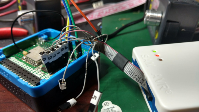
The most difficult thing is figuring out the pins to connect. Unfortunately the LoRa module has the ISP connections in a line rather than the standard connection. Adding to the frustration is the fact that the DuPont pins on the octopus cable have taped-on numbers. Although it is handy having the connections labeled, the thickness of the tape makes having 6 of them in a row a very tight fit:
As a feature request, I hope the M5Stack folks consider implementing a standard SPI / ICSP connector:
In the meantime, it would probably be worthwhile to create a custom inline Dupont header using a kit such as this and this crimping tool. (this is incredibly handy to have)
The single most important thing is that: MO = MOSI = TDI (I wasted a bunch of time when I had assumed MO = MisO = TDO; which is not correct!). Also note that nTRST != nSRST. (yes, I made that mistake, too; my original screen clip did not include the SPI column which makes this more obvious).
These are the correct connections for debugWIRE, aka SPI, aka ISP programming of the M5Stack LoRa ATMEGA328P:
Note that VTG is not suited to power a remote device. This is a power sensor to determine logic voltage levels. Devices being debugged, including this LoRa module most be self powered!
void setup() {
  // put your setup code here, to run once:
  Serial.begin(115200);
}

void loop() {
  // put your main code here, to run repeatedly:
 Serial.println("hello");
}
Then in Atmel Studio: File - New - Project:
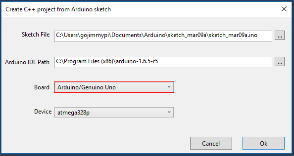
Select "Create project from Arduino sketch", edit directories as needed, then press ok. Next select the file location of the Arduino sketch. Be sure to select Arduino/Genuino Uno for Board:
It may take a short while to create a project.
Once the project is created, click Project - {name} Properties (Alt-F7). Select Atmel ICE Debugger and ensure Debug Wire is selected for interface:
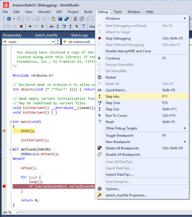
Next - click Debug - Step Into. The first time, there will likely be a warning about fuse settings:
Press Yes to set the fuses appropriately. If you get any other errors, check the wiring. Then recheck the wiring.
If successful, there will be a message that debugWIRE is enabled. BE SURE TO READ THE MESSAGE:
Note that you MUST power cycle the Mega328 (in our case the M5Stack & LoRa). Do not power cycle the Atmel ICE debugger.
Press ok, and VOILA!
I recall reading that the ATMega328 *must* have debugging properly disabled upon completion or Really Bad Things might happen (really?). I still do this, although I've never actually tested it to be sure. While paused at a breakpoint, click Disable debugWIRE and Close.
So the next step will be seeing if I can get the RadioHead drivers working on this new LoRa module... but first I'd like to get the LoRa AVR serial port working.
M5Stack RSSI is a solid RSSI strength of 10 points worse than the exact same code on 32u4 which has the exact same RA-02 AI-Thinker LoRa device.
Recall from previous blog, LoRa RST and IRQ are reversed. (RST is actually GPIO36 input only; unusable). Otherwise it would have been: Beep = LoRa reset.
M5Stack Speaker (GPIO25) is shared with LoRa Interrupt. (beep = interrupt?)
The M5Stack display shares the NSS pin with the LoRa module. (poke registers with care!)
The receiver and transmitter need to be configured EXACTLY the same for best range (more than just the same frequency); but this was not the problem with our poor RSSI
My LoRa-GPIO project and required RadioHead and M5Stack libraries merged to master on GitHub
When updating library (include) code, Visual Studio apparently does not look at file dates and may use previous compiled code; clean project after library changes.
The latest working (although not very pretty) Very Remote Lora-GPIO Control and Monitoring Project code has been merged onto my master branch.
I've merged my M5Stack development branch back to my RadioHead master branch. This was a "Squash and Merge". Normally I like to keep the history... but as the RadioHead owners prefer a single patch file, perhaps this will be better. Time will tell. History is still in the branch.
My M5Stack library fork is, and has been up to date on the master branch. (no branches)
The main LoRa-GPIO solution contains several projects as noted in the GitHub readme. These are all Arduino-style projects using the really awesome VisualMicro add-in for Visual Studio.
I've been reading through the ARRL Ham Radio License manual. I don't know if I will actually get a ham license, but wow - what a great book this is to cover the essentials of what you need to know for RF communications (such as the LoRa for this project). Although I had a ton of classes in college covering a wide variety of electronics, electromagnetism, communications, even an entire class on antenna theory... this ARRL book contains a lot of relatively straightforward, every-day language on the practical essentials of radio frequency communication - all in one place. The ARRL web site also has some excellent resources. Ok, there's also pretty much NO math, NO theory: Just useful facts. So this is certainly not a book for how or why or how to apply to new problem. Still, it is a quite good book. Highly recommended & would make a great gift for someone new to the field.
So on to the testing... now that I have the RadioHead drivers working, I actually went back to the M5Stack example code (Sandeep drivers renamed M5LoRa). Recall that I have the RadioHead drivers on a remote 32u4 sending LoRa packets. Here's the sample code for the M5Stack receiver (Arduino: File - Examples - M5Stack - Modules - LoRa - LoRaReceiver) :
#include
#include

#define LORA_CS_PIN   5
#define LORA_RST_PIN  26
#define LORA_IRQ_PIN  36

void setup() {

  M5.begin();

  // override the default CS, reset, and IRQ pins (optional)
  LoRa.setPins(LORA_CS_PIN, LORA_RST_PIN, LORA_IRQ_PIN); // set CS, reset, IRQ pin
  Serial.println("LoRa Receiver");
  M5.Lcd.println("LoRa Receiver");

  // frequency in Hz (433E6, 866E6, 915E6)
  if (!LoRa.begin(433E6)) {
    Serial.println("Starting LoRa failed!");
    M5.Lcd.println("Starting LoRa failed!");
    while (1);
  }

  // LoRa.setSyncWord(0x69);
  Serial.println("LoRa init succeeded.");
  M5.Lcd.println("LoRa init succeeded.");
}

void loop() {
  // try to parse packet
  int packetSize = LoRa.parsePacket();
  if (packetSize) {
    // received a packet
    Serial.print("Received packet: \"");
    M5.Lcd.print("Received packet: \"");

    // read packet
    while (LoRa.available()) {
      char ch = (char)LoRa.read();
      Serial.print(ch);
      M5.Lcd.print(ch);
    }

    // print RSSI of packet
    Serial.print("\" with RSSI ");
    Serial.println(LoRa.packetRssi());
    M5.Lcd.print("\" with RSSI ");
    M5.Lcd.println(LoRa.packetRssi());
  }
}
This code writes to both the M5Stack display as well as the serial port. The display is cool as I don't need to remember to disconnect the serial port when reprogramming. HOWEVER: You may recall from my previous blog that the M5Stack display *and* LoRa module share the NSS (slave select) pin. That simply sounds dangerous (and indeed I observed some display oddities), so I put M5Stack LoRa to sleep when writing to the display.
The shocking thing here is that there's up to a difference of TEN in RSSI values as compared to using the RadioHead drivers. (RSSI 36 vs 26). As this is a log scale, that's a 10x difference in power! Now - this is not to say that the Sandeep library has a problem just because it is polling rather than using interrupts. It is a matter of default configuration. I picked apart the RadioHead control register libraries and added a note about the matching importance:
When printing the register values from the Sandeep (M5LoRa) library, (move the readRegister from the private to public section)...
There's a SINGLE BIT different (CRC not enabled!): 0x72, 0x70, 0x4 - alas that didn't seem to make much of a substantial difference in RSSI values. I supposed I had expected different error coding, spreading factor, or some other obvious difference.
I confirmed the running values of RadioHead cinfig registers are also 0x72, 0x70, 0x4 - but the RSSI is typically -25 whereas the Sandeep (M5Lora) drivers report an RSSI of typically -35!
So the next thing is: how to each of them calculate RSSI?
// Remember the last signal to noise ratio, LORA mode
// Per page 111, SX1276/77/78/79 datasheet
_lastSNR = (int8_t)spiRead(RH_RF95_REG_19_PKT_SNR_VALUE) / 4;

// Remember the RSSI of this packet, LORA mode
// this is according to the doc, but is it really correct?
// weakest receiveable signals are reported RSSI at about -66
_lastRssi = spiRead(RH_RF95_REG_1A_PKT_RSSI_VALUE);
// Adjust the RSSI, datasheet page 87
if (_lastSNR < 0)
 _lastRssi = _lastRssi + _lastSNR;
else
 _lastRssi = (int)_lastRssi * 16 / 15;
if (_usingHFport)
 _lastRssi -= 157;
else
 _lastRssi -= 164;
Grr... So ok, the difference in RSSI appears to be simply a different calculation. The real test is: how far away can the units be and still communicate? I'm still happy I have the RadioHead libraries working. In my opinion is is clearly the superior code.
So reference check: after all the code changes, let's try same units: 32u4 to 32u4. Cleaned project, full rebuild. RSSI value is -19 or -20! Rechecking the M5Stack, RSSI is -27. So even with the same codebase and same calcs, the M5Stack LoRa has a poorer RSSI value. Using an external battery power source and the value improves to RSSI = -24.
So, as mentioned about - I've been reading about real world antennas, so perhaps the M5Stack antenna has an issue. Well, I tried that as well, replacing the internal antenna with one of those external antennas - identical to the one on the 32u4. Still there's a discrepancy in RSSI values between the two devices.
What else? Ok, so there's a speaker in the M5Stack. Poking around with that, defined in:
libraries\M5Stack\src\utility\Config.h
there's a declaration:
// BEEP PIN
#define SPEAKER_PIN 25
Ah yes, GPIO25, our friend. The LoRa interrupt pin. (sigh)
So perhaps all the extras in the M5Stack are indeed causing a problem. I tried to disable a few things such as the speaker init, but no luck. I do however, have another Console (without display) app that is specifically targeted for the 32u4, but with the magic of simply changing platforms in the IDE, can be recompiled and sent to the M5Stack! RSSI about that same at -27 (ranging from -23 to -29). Replace with the exact same code on the 32u4 and the RSSI is a full 10 points better at -17. (10x improvement in signal strength!).
I tried another M5Stack unit with a different LoRa module. Same result.
So at this point, I really believe it is a hardware issue. I've been unable to get a copy of the schematic for the M5Stack LoRa module, However the 32u4 has a pin connection diagram here.
As soon as hardware is questioned - the first thing to do is of course add some capacitors! I added a 10uF and a 10pf cap directly to the power input to the RA-02.
In the pic, you can see I fished a new, external antenna along with the new caps. And ya, I got a little close to the side of the M5 Lora module.
Additionally I added a shield (aluminum foil sandwiched between two layers of clear packing tape) to both sides of the LoRa module. After all - there is an ESP32 microprocessor buzzing away just on the other side of the PCB!
The first field test was a relative success! I more than doubled the original range! Ok, so I didn't actually test after each change, so I don't know exactly which was the most effective in extending the range.
Note the Semtech site has a bunch of LoRa resources, including this cool LoRa calculator (I will include in my GitHub repository in the docs container, in case the link to Semtech ever breaks.
Note that I am currently transmitting at 125kHz. Lowering this increases range! Lower this to about 15.6kHz and you get another 10db in "link performance". (in theory).
Overall I am quite happy with the result. Ok, I'm not seeing multi-kilometer ranges. But that's also line-of-sight. My transmitter is on the kitchen table - with the entire garage between it and the M5Stack receiver. Next test will be from line of site.
The super exciting thing is I have a prototype from the kind folks at M5Stack arriving in the mail soon for the next potential version of the LoRa module. I am quite interested in seeing how well it performs.
Stay tuned for my next blog where I work on the prototype V2 LoRa modules with its own embedded ATMEGA328.
The M5Stack LoRa is using Sandeep drivers (polling) whereas RadioHead drivers use interrupts.
The M5Stack LoRa board has IRQ/RST reversed! IRQ DIO0 is actually connected to GPIO26. RST is actually connected to GPIO36, but is useless since GPIO36 is input only.
The M5Stack display shares NSS on GPIO5; LoRa needs to be put to sleep when updating display. (Mutex likely needed in FreeRTOS)
My LoRa32u4 is using the RadioHead libraries; The M5Stack uses a slightly modified Sandeep library. A pair of LoRa32u4 units work great. A LoRa32u4 sending to M5Stack - not so great. So I'm attempting to use the RadioHead library with the M5Stack.
To install M5Stack library with ability to save in GitHub and submit pull requests. First fork the project to your own
GitHub repository. Then clone it to your Arduino library (in my case, gojimmypi user)
cd C:\Users\gojimmypi\Documents\Arduino\libraries\
git clone https://github.com/gojimmypi/M5Stack.git
:: optionally get RadioHead drivers from Adafruit
:: ren RadioHead RadioHead-stock
git clone https://github.com/gojimmypi/RadioHead.git
cd C:\Users\gojimmypi\Documents\Arduino\libraries\
mkdir temp-adafruit
cd temp-adafruit
git clone https://github.com/adafruit/RadioHead.git
cd RadioHead
xcopy *.* ..\..\RadioHead\*.* /s /d
:: reminder to delete temp-adafruit
In my case, after the fork from Adafruit, I deleted everything (except hidden .git directory, of course) and copied back the contents of the RadioHead-stock directory so we could use Visual Studio diff (right-click, Compare with Unmodified). Not unexpected, the RadioHead I had was older. So I fetched the Adafruit into a temp directory, then copied it back:
Visual Studio users will be happy to know there's a feature to use File Explorer; right click on the directory and select "open in Visual Studio". With the GitHub extension installed, there's a very nice GUI for GitHub.
To add the RadioHead libraries to an M5 Stack project: vMicro - Add Library - User - RadioHead:
After spending a ton of time trying to get the RadioHead drivers working, first I found that that M5Stack base I was using had completely inoperable GPIO35 and GPIO36 pins. After swapping that out for a new one... and even more time spent trying to get RadioHead drivers working - I discovered another WIRING problem. <sigh> Connections to GPIO26 and GPIO36 are reversed! Not all coding problems are based solely in software.
Here's the corrected M5Stack LoRa pinout diagram:
Note that the RST (reset) input to the RA-02 LoRa device won't actually reset, as GPIO36 is input only!
Many thanks to Jimmy Lai at M5Stack for sending me a prototype of their next version of LoRa. Looking forward to my next gizmo in the mail :)